ECL Comfort 210/310, A275/A375 Installation Guide - Danfoss ...
ECL Comfort 210/310, A275/A375 Installation Guide - Danfoss ...
ECL Comfort 210/310, A275/A375 Installation Guide - Danfoss ...

You also want an ePaper? Increase the reach of your titles
YUMPU automatically turns print PDFs into web optimized ePapers that Google loves.
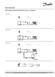
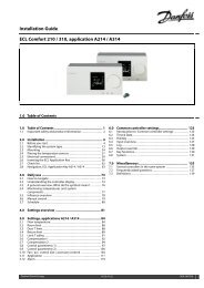
<strong>Installation</strong> <strong>Guide</strong> <strong>ECL</strong> <strong>Comfort</strong> <strong>210</strong> / <strong>310</strong>, application <strong>A275</strong> / <strong>A375</strong><br />
The application <strong>A275</strong>.3 is very flexible. These are the basic<br />
principles:<br />
DHW (circuit 3):<br />
By means of a week schedule (up to 3 ‘<strong>Comfort</strong>’ periods / day), the<br />
DHW circuit can be in ‘<strong>Comfort</strong>’ or ‘Saving’ mode (two different<br />
temperature values for desired DHW temperature).<br />
If the measured DHW temperature (S6) is lower than the desired<br />
DHW temperature, the DHW heating procedure starts:<br />
• The circulation pump P1 in the heating circuit is switched OFF<br />
• The DHW heating pump P3 is switched ON<br />
• The desired boiler temperature at S3 is increased.<br />
The desired boiler temperature is typically 10 -15 degrees higher<br />
than the desired DHW temperature.<br />
When the measured DHW temperature (S6) gets higher than the<br />
desired DHW temperature, the DHW heating pump (P3) is switched<br />
OFF. Start and stop differences determine the ON / OFF control. A<br />
post-run time can be set.<br />
An anti-bacteria function is available for activation on the selected<br />
days of the week.<br />
The DHW heating has priority, i.e. pump P3 is ON and pump P1 is<br />
OFF. If the application has a changeover valve (priority valve) for<br />
the DHW heating, the circulation pump P1 is still ON during DHW<br />
heating.<br />
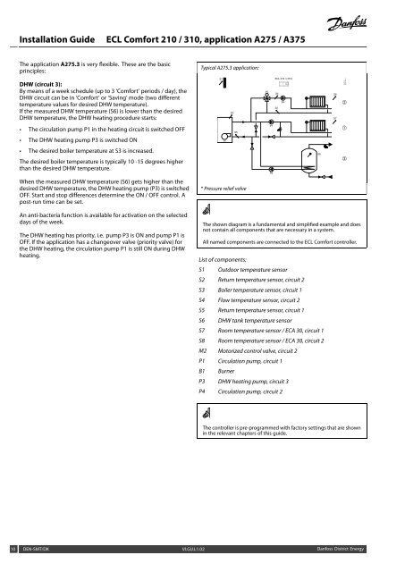
Typical <strong>A275</strong>.3 application:<br />
S1<br />
B1<br />
S3<br />
S5<br />
* Pressure relief valve<br />
M2<br />
P1<br />
P3<br />
<strong>ECL</strong> <strong>210</strong> / (<strong>310</strong>)<br />
S4<br />
S2<br />
The shown diagram is a fundamental and simplified example and does<br />
not contain all components that are necessary in a system.<br />
All named components are connected to the <strong>ECL</strong> <strong>Comfort</strong> controller.<br />
List of components:<br />
S1 Outdoor temperature sensor<br />
S2 Return temperature sensor, circuit 2<br />
S3 Boiler temperature sensor, circuit 1<br />
S4 Flow temperature sensor, circuit 2<br />
S5 Return temperature sensor, circuit 1<br />
S6 DHW tank temperature sensor<br />
S7 Room temperature sensor / ECA 30, circuit 1<br />
S8 Room temperature sensor / ECA 30, circuit 2<br />
M2 Motorized control valve, circuit 2<br />
P1 Circulation pump, circuit 1<br />
B1 Burner<br />
P3 DHW heating pump, circuit 3<br />
P4 Circulation pump, circuit 2<br />
The controller is pre-programmed with factory settings that are shown<br />
in the relevant chapters of this guide.<br />
10 DEN-SMT/DK VI.GU.L1.02 <strong>Danfoss</strong> District Energy<br />
P4<br />
*<br />
S6<br />
S8<br />
S7<br />
②<br />
①<br />
③<br />
<strong>Danfoss</strong><br />
87H2169.10