ECL Comfort 210/310, A275/A375 Installation Guide - Danfoss ...
ECL Comfort 210/310, A275/A375 Installation Guide - Danfoss ...
ECL Comfort 210/310, A275/A375 Installation Guide - Danfoss ...

You also want an ePaper? Increase the reach of your titles
YUMPU automatically turns print PDFs into web optimized ePapers that Google loves.
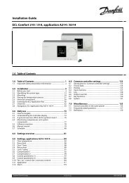
<strong>Installation</strong> <strong>Guide</strong> <strong>ECL</strong> <strong>Comfort</strong> <strong>210</strong> / <strong>310</strong>, application <strong>A275</strong> / <strong>A375</strong><br />
8.6 Output override<br />
This section describes the function in general for the <strong>ECL</strong> <strong>Comfort</strong><br />
<strong>210</strong> / <strong>310</strong> series. The shown displays are typical and not application<br />
related. They might differ from the displays in your application.<br />
The output override is used to disable one or more of the controlled<br />
components. This could among others be useful in a service<br />
situation.<br />
Action: Purpose: Examples:<br />
Choose 'MENU' in any of the overview<br />
displays<br />
Confirm<br />
Choose the circuit selector at the top<br />
right corner in the display<br />
Confirm<br />
Choose common controller settings<br />
Confirm<br />
Choose 'Output override'<br />
Confirm<br />
Choose a controlled component M1, P1 etc.<br />
Confirm<br />
Adjust the status of the controlled<br />
component:<br />
Motorized control valve: AUTO, STOP,<br />
CLOSE, OPEN<br />
Pump: AUTO, OFF, ON<br />
Confirm status change<br />
Remember to change the status back again as soon as an override<br />
is not required any longer.<br />
Controlled components Circuit selector<br />
When the selected controlled component (output) is not ‘AUTO’, the<br />
<strong>ECL</strong> <strong>Comfort</strong> controller does not control the component in question<br />
(pump or motorized control valve e.g.). Frost protection is not active.<br />
When output override of a controlled component is active the symbol<br />
‘ ! ’ is shown to the right of the mode indicator in the enduser displays.<br />
<strong>Danfoss</strong> District Energy VI.GU.L1.02 DEN-SMT/DK 161