ECL Comfort 210/310, A275/A375 Installation Guide - Danfoss ...
ECL Comfort 210/310, A275/A375 Installation Guide - Danfoss ...
ECL Comfort 210/310, A275/A375 Installation Guide - Danfoss ...

You also want an ePaper? Increase the reach of your titles
YUMPU automatically turns print PDFs into web optimized ePapers that Google loves.
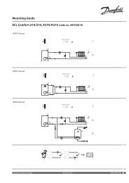
<strong>Installation</strong> <strong>Guide</strong> <strong>ECL</strong> <strong>Comfort</strong> <strong>210</strong> / <strong>310</strong>, application <strong>A275</strong> / <strong>A375</strong><br />
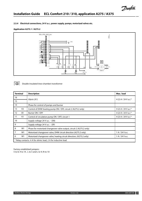
2.5.4 Electrical connections, 24 V a.c., power supply, pumps, motorized valves etc.<br />
Application <strong>A275</strong>.1 / <strong>A275</strong>.2<br />
Double-insulated (two-chamber) transformer<br />
Terminal Description Max. load<br />
16<br />
15<br />
Alarm (A1) 4 (2) A / 24 V a.c.*<br />
14 Phase for control of pumps and burner<br />
13 K3 Control of DHW heating pump ON / OFF, circuit 2 (<strong>A275</strong>.2 only) 4 (2) A / 24 V a.c.*<br />
12 B1 Burner ON / OFF 4 (2) A / 24 V a.c.*<br />
11 K1 Control of circulation pump ON / OFF, circuit 1 4 (2) A / 24 V a.c.*<br />
10 Supply voltage 24 V a.c. - (SN)<br />
9 Supply voltage 24 V a.c. - (SP)<br />
8 M1 Phase for motorized changeover valve output, circuit 2 (<strong>A275</strong>.2 only)<br />
7 M1 Motorized changeover valve, DHW circuit direction (<strong>A275</strong>.2 only) 1 A / 24 V a.c.<br />
6 M1 Motorized changeover valve, heating circuit direction, (<strong>A275</strong>.2 only) 1 A / 24 V a.c.<br />
* Relay contacts: 4 A for ohmic load, 2 A for inductive load<br />
Factory established jumpers:<br />
5 to 8, 9 to 14 , L to 5 and L to 9, N to 10<br />
<strong>Danfoss</strong> District Energy VI.GU.L1.02 DEN-SMT/DK 61