- Page 1 and 2: e200z1 Power Architecture Core Refe
- Page 3 and 4: Contents Paragraph Number Title Con
- Page 5 and 6: Contents Paragraph Number Title e20
- Page 7 and 8: Contents Paragraph Number Title e20
- Page 9 and 10: Contents Paragraph Number Title e20
- Page 11 and 12: Contents Paragraph Number Title e20
- Page 13 and 14: Figures Figure Number Title e200z1
- Page 15 and 16: Figures Figure Number Title e200z1
- Page 17 and 18: Tables Table Number Title e200z1 Po
- Page 19 and 20: Tables Table Number Title e200z1 Po
- Page 21 and 22: Chapter 1 e200z1 Overview 1.1 Overv
- Page 23 and 24: e200z1 Power Architecture Core Refe
- Page 25 and 26: e200z1 Power Architecture Core Refe
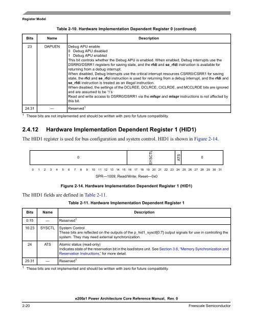
- Page 27 and 28: Chapter 2 Register Model This secti
- Page 29 and 30: PSU Registers 1 PSU PSCR PSSR PSHR
- Page 31 and 32: e200z1 Power Architecture Core Refe
- Page 33 and 34: e200z1 Power Architecture Core Refe
- Page 35 and 36: 17 (49) 18 (50) 19 (51) 20 (52) 21
- Page 37 and 38: e200z1 Power Architecture Core Refe
- Page 39 and 40: 8 (40) 9 (41) 10 (42) 11 (43) 12 (4
- Page 41 and 42: e200z1 Power Architecture Core Refe
- Page 43 and 44: 2.4.9 Timer Status Register (TSR) e
- Page 45: 14 ICR Interrupt Inputs Clear Reser
- Page 49 and 50: Table 2-14. Additional Synchronizat
- Page 51 and 52: Mnemonic Name Table 2-15. Special P
- Page 53 and 54: Table 2-16. Reset Settings for e200
- Page 55 and 56: Chapter 3 Instruction Model This ch
- Page 57 and 58: 3.5 Memory Access Alignment Support
- Page 59 and 60: e200z1 Power Architecture Core Refe
- Page 61 and 62: e200z1 Power Architecture Core Refe
- Page 63 and 64: 3.12.1 Instruction Index Sorted by
- Page 65 and 66: Format Primary (Inst 0:5) Opcode e2
- Page 67 and 68: Format Primary (Inst 0:5) Opcode X
- Page 69 and 70: Format Primary (Inst 0:5) Opcode X
- Page 71 and 72: Format Primary (Inst 0:5) Opcode XL
- Page 73 and 74: Format Primary (Inst 0:5) Opcode Ta
- Page 75 and 76: Format Primary (Inst0:5) Opcode Ext
- Page 77 and 78: Format Primary (Inst0:5) Opcode Ext
- Page 79 and 80: Format Primary (Inst0:5) Opcode Ext
- Page 81 and 82: Format Primary (Inst0:5) Opcode Ext
- Page 83 and 84: Format Primary (Inst0:5) Opcode Ext
- Page 85 and 86: e200z1 Power Architecture Core Refe
- Page 87 and 88: Chapter 4 Instruction Pipeline and
- Page 89 and 90: 4.1.2 Instruction Unit e200z1 Power
- Page 91 and 92: Figure 4-2. Pipeline Diagram 4.3.1
- Page 93 and 94: e200z1 Power Architecture Core Refe
- Page 95 and 96: Time Slot 1st LD inst. IFETCH DEC /
- Page 97 and 98:
e200z1 Power Architecture Core Refe
- Page 99 and 100:
e200z1 Power Architecture Core Refe
- Page 101 and 102:
4.5.1 Completion Serialization e200
- Page 103 and 104:
e200z1 Power Architecture Core Refe
- Page 105 and 106:
4.7 Instruction Timings e200z1 Powe
- Page 107 and 108:
Chapter 5 Interrupts and Exceptions
- Page 109 and 110:
Interrupt Type e200z1 Power Archite
- Page 111 and 112:
14 (46) 15 (47) 16:23 (48:55) 5.3 M
- Page 113 and 114:
23 (55) 24 (56) 25 (57) 26 (58) 27
- Page 115 and 116:
e200z1 Power Architecture Core Refe
- Page 117 and 118:
MSR UCLE 0 WE 0 CE 0 EE 0 PR 0 ESR
- Page 119 and 120:
e200z1 Power Architecture Core Refe
- Page 121 and 122:
5.7.5 External Input Interrupt (IVO
- Page 123 and 124:
e200z1 Power Architecture Core Refe
- Page 125 and 126:
Table 5-18 lists register settings
- Page 127 and 128:
Table 5-21 lists register settings
- Page 129 and 130:
e200z1 Power Architecture Core Refe
- Page 131 and 132:
e200z1 Power Architecture Core Refe
- Page 133 and 134:
e200z1 Power Architecture Core Refe
- Page 135 and 136:
21 22 3 23 24 25 Data Storage 1. Ac
- Page 137 and 138:
e200z1 Power Architecture Core Refe
- Page 139 and 140:
Chapter 6 Memory Management Unit 6.
- Page 141 and 142:
e200z1 Power Architecture Core Refe
- Page 143 and 144:
e200z1 Power Architecture Core Refe
- Page 145 and 146:
21:25 [53:57] 26:27 [58:59] 28:29 [
- Page 147 and 148:
6.5 Software Interface and TLB Inst
- Page 149 and 150:
6.5.4 TLB Invalidate (tlbivax) Inst
- Page 151 and 152:
e200z1 Power Architecture Core Refe
- Page 153 and 154:
6.7.2 MMU Control and Status Regist
- Page 155 and 156:
Table 6-10. MAS1—Descriptor Conte
- Page 157 and 158:
The MAS3 register is shown in Figur
- Page 159 and 160:
6.7.4 MAS Registers Summary The MAS
- Page 161 and 162:
6.9 Core Interface Operation for MM
- Page 163 and 164:
Chapter 7 Core Complex Interfaces T
- Page 165 and 166:
Address Bus Transfer Control Transf
- Page 167 and 168:
Table 7-1. External Interface Signa
- Page 169 and 170:
j_lsrl_regsel O 0 External LSRL reg
- Page 171 and 172:
p_sprnum[0:9] O — Global SPR addr
- Page 173 and 174:
e200z1 Power Architecture Core Refe
- Page 175 and 176:
7.3.4.1 Transfer Type (p_d_htrans[1
- Page 177 and 178:
Table 7-8. p_[d,i]_hprot[5:0] Prote
- Page 179 and 180:
e200z1 Power Architecture Core Refe
- Page 181 and 182:
B. E. Word @001 0 0 1 1 0 0 B. E. W
- Page 183 and 184:
e200z1 Power Architecture Core Refe
- Page 185 and 186:
e200z1 Power Architecture Core Refe
- Page 187 and 188:
0 1 1 0 1 x x Reserved 0 1 1 1 0 x
- Page 189 and 190:
7.3.12.2 Processor Halt Request (p_
- Page 191 and 192:
7.3.14.1 OnCE Enable (jd_en_once) e
- Page 193 and 194:
1 j_tdo_en is asserted when the TAP
- Page 195 and 196:
7.3.15.14 Register Select (j_gp_reg
- Page 197 and 198:
e200z1 Power Architecture Core Refe
- Page 199 and 200:
e200z1 Power Architecture Core Refe
- Page 201 and 202:
e200z1 Power Architecture Core Refe
- Page 203 and 204:
Clock 2 (C2): e200z1 Power Architec
- Page 205 and 206:
7.4.1.5 Read and Write Transfers Fi
- Page 207 and 208:
e200z1 Power Architecture Core Refe
- Page 209 and 210:
7.4.1.6 Misaligned Accesses e200z1
- Page 211 and 212:
e200z1 Power Architecture Core Refe
- Page 213 and 214:
Figure 7-15 illustrates functional
- Page 215 and 216:
Figure 7-15 illustrates functional
- Page 217 and 218:
e200z1 Power Architecture Core Refe
- Page 219 and 220:
m_clk p_htrans p_addr,p_hprot p_hsi
- Page 221 and 222:
e200z1 Power Architecture Core Refe
- Page 223 and 224:
e200z1 Power Architecture Core Refe
- Page 225 and 226:
e200z1 Power Architecture Core Refe
- Page 227 and 228:
m_clk p_tbclk p_tbdisable t_tbclk_h
- Page 229 and 230:
Chapter 8 Power Management 8.1 Powe
- Page 231 and 232:
e200z1 Power Architecture Core Refe
- Page 233 and 234:
Chapter 9 Debug Support This chapte
- Page 235 and 236:
e200z1 Power Architecture Core Refe
- Page 237 and 238:
9.2.1 Instruction Address Compare E
- Page 239 and 240:
9.2.5 Branch Taken Debug Event e200
- Page 241 and 242:
9.2.13 Unconditional Debug Event e2
- Page 243 and 244:
Table 9-1 provides bit definitions
- Page 245 and 246:
9.3.3.2 Debug Control Register 1 (D
- Page 247 and 248:
9.3.3.3 Debug Control Register 2 (D
- Page 249 and 250:
e200z1 Power Architecture Core Refe
- Page 251 and 252:
Table 9-4. DBCR3 Bit Definitions (c
- Page 253 and 254:
posted, but the counter value will
- Page 255 and 256:
e200z1 Power Architecture Core Refe
- Page 257 and 258:
e200z1 Power Architecture Core Refe
- Page 259 and 260:
e200z1 Power Architecture Core Refe
- Page 261 and 262:
e200z1 Power Architecture Core Refe
- Page 263 and 264:
Table 9-7 provides bit definitions
- Page 265 and 266:
Table 9-9 indicates the e200 OnCE r
- Page 267 and 268:
Table 9-10 provides bit definitions
- Page 269 and 270:
Table 9-11 provides a list of acces
- Page 271 and 272:
9.4.7.4 Debug Request During Waitin
- Page 273 and 274:
9.4.8.2 Control State Register (CTL
- Page 275 and 276:
IRStat5—IR Status Bit 5 IRStat6
- Page 277 and 278:
e200z1 Power Architecture Core Refe
- Page 279 and 280:
To single-step the CPU: e200z1 Powe
- Page 281 and 282:
. 9.7.2 Parallel Signature Status R
- Page 283 and 284:
Appendix A Register Summary Conditi
- Page 285 and 286:
e200 z1 0 Figure A-3. e200 Supervis
- Page 287 and 288:
0 e200z1 Power Architecture Core Re
- Page 289 and 290:
* Figure A-27. CPU Scan Chain Regis
- Page 291 and 292:
M A S 0 M A S 1 M A S 2 M A S 3 M A
- Page 293 and 294:
Appendix B Revision History This ap
- Page 295 and 296:
Glossary The glossary contains an a
- Page 297 and 298:
Copy-back operation. A cache operat
- Page 299 and 300:
Local access window. Mapping used t
- Page 301 and 302:
Physical medium attachment (PMA) su
- Page 303 and 304:
Set (n). A subdivision of a cache.
- Page 305 and 306:
A Alignment exception, 5-15 B Branc