- Page 1 and 2:
Forward Contents How To Use This Ma
- Page 3 and 4:
How to Use This Manual This service
- Page 5 and 6:
MODEL ILLUSTRATION JET 50 / 100 Ser
- Page 9:
1. GENERAL INFORMATION General Safe
- Page 14 and 15:
Torque values 1. GENERAL INFORMATIO
- Page 17 and 18:
1. GENERAL INFORMATION 1-10 Starter
- Page 19 and 20:
1. GENERAL INFORMATION 1-12 Fuel pu
- Page 21 and 22:
1. GENERAL INFORMATION B. Engine ru
- Page 23 and 24:
1. GENERAL INFORMATION E. CLUTCH, D
- Page 25:
1. GENERAL INFORMATION Note: 1-18 T
- Page 30:
Oil Pump Control Cable Caution To a
- Page 35 and 36:
2. SERVICE MAINTENANCE INFORMATION
- Page 39 and 40:
2. SERVICE MAINTENANCE INFORMATION
- Page 41 and 42:
3. LUBRICATION SYSTEM Precautions I
- Page 43 and 44:
3. LUBRICATION SYSTEM Oil Pump/Oil
- Page 45 and 46:
3. LUBRICATION SYSTEM NOTES: 3-6 Th
- Page 47 and 48:
4. ENGINE REMOVAL Engine removal Re
- Page 49 and 50:
4. ENGINE REMOVAL Remove engine mou
- Page 51 and 52:
5. CYLINDER HEAD/CYLINDER/PISTON Ma
- Page 53 and 54:
5. CYLINDER HEAD/CYLINDER/PISTON Cy
- Page 55 and 56:
5. CYLINDER HEAD/CYLINDER/PISTON Us
- Page 58:
Maintenance Information ·····
- Page 61 and 62:
6. ALTERNATOR Disconnect alternator
- Page 63 and 64:
7. “V” TYPE BELT DRIVE SYSTEM/K
- Page 65 and 66:
7. “V” TYPE BELT DRIVE SYSTEM/K
- Page 67 and 68:
7. “V” TYPE BELT DRIVE SYSTEM/K
- Page 69 and 70:
7. “V” TYPE BELT DRIVE SYSTEM/K
- Page 71 and 72:
7. “V” TYPE BELT DRIVE SYSTEM/K
- Page 73 and 74:
7. “V” TYPE BELT DRIVE SYSTEM/K
- Page 75 and 76:
7. “V” TYPE BELT DRIVE SYSTEM/K
- Page 78 and 79:
Disassembly of Final Driving Mechan
- Page 80 and 81:
Install countershaft, final driven
- Page 82:
Maintenance Information······
- Page 85 and 86:
9. CRANKCASE/CRANKSHAFT Crankshaft
- Page 87 and 88:
9. CRANKCASE/CRANKSHAFT Assemble th
- Page 90:
Throttle Valve Removal Remove the b
- Page 94 and 95:
Flaot Level Inspection Measure floa
- Page 96 and 97:
Air Cleaner Removal/Installation Lo
- Page 98 and 99:
Front Disc Brake System ·····
- Page 100 and 101:
Maintenance Information Precautions
- Page 102 and 103:
Hydraulic Disc Brake Close the drai
- Page 104 and 105: Brake Disc Inspection Visually chec
- Page 106 and 107: Install the rubber pad into the gro
- Page 108 and 109: Installation Apply with a thin coat
- Page 110 and 111: Body Overview ··········
- Page 112 and 113: Side Covers 1. Removal: Remove 3 s
- Page 114 and 115: Remove 2 screw form of the body cov
- Page 117 and 118: 12. BODY COVER Front Inner Box 1. R
- Page 119 and 120: 12. BODY COVER Steering Handle Cove
- Page 121 and 122: 12. BODY COVER Note: 12-12 This cha
- Page 124 and 125: Steering Handle Removal Remove hand
- Page 126 and 127: Inspection Place the axle onto a V-
- Page 128 and 129: Lubricate the speedometer gear with
- Page 130 and 131: Front Fork Removal Handle Front w
- Page 132 and 133: Maintenance Information······
- Page 134 and 135: Rear Wheel Remove Remove exhaust pi
- Page 136 and 137: Maintenance Information······
- Page 138: Troubleshooting No voltage Battery
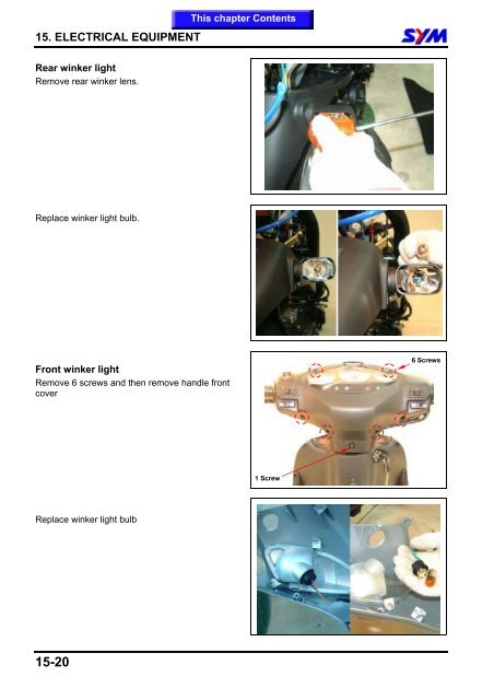
- Page 141: 15. ELECTRICAL EQUIPMENT Current Le
- Page 149 and 150: 15. ELECTRICAL EQUIPMENT Starter Mo
- Page 152 and 153: Switch / Horn Remove handle covers
- Page 156 and 157: Clock unit - JET EURO 50/100 Remove
- Page 158 and 159: JET 50 ELECTRICAL DIAGRAM Home page
- Page 160 and 161: JET 100 ELECTRICAL DIAGRAM Home pag