

EN: man_8055tco_user.pdf - Fagor Automation
EN: man_8055tco_user.pdf - Fagor Automation
EN: man_8055tco_user.pdf - Fagor Automation

You also want an ePaper? Increase the reach of your titles
YUMPU automatically turns print PDFs into web optimized ePapers that Google loves.
3.3.3 Associated subroutine<br />
The OEM must define the subroutine associated with the cycle (refer to the<br />
programming <strong>man</strong>ual). It must contain all the necessary instructions to run the<br />
canned cycle.<br />
There is one subroutine associated with each cycle. Subroutine 9001 corresponds<br />
to cycle 001, 9002 to 002 and so on up to 9200 that corresponds to cycle 200.<br />
When the configuration file of the cycle uses an instruction like (P100=W13), the<br />
auxiliary subroutine must also be defined.<br />
There is one auxiliary subroutine associated with each cycle. Subroutine 9301<br />
corresponds to cycle 001, 9302 to 002 and so on up to 9500 that corresponds to cycle<br />
200.<br />
Therefore, the 2 subroutines associated with the cycle are:<br />
The basic subroutine associated with the cycle9000 + cycle number<br />
The auxiliary subroutine associated with the cycle9300 + cycle number.<br />
When executing the cycle, its associated subroutine is called upon indicating in local<br />
parameters A - Z (P0 - P25) the value used to define each field.<br />
Parameter A (P0) indicates the value of the W1 field, B (P1) that of the W2 field and<br />
so on up to Z (P25) that indicates the value of the W26 field. If there are more fields,<br />
use global parameters.<br />
The data shown by each parameter depends on the type of associated data.<br />
If it is a numeric data (coordinates, feedrate, etc.) ...............The value assigned<br />
If it is the number of a profile ................................................The value assigned<br />
(the call to the profile must be done in the subroutine)<br />
It is one of several available options (group of buttons).......... Values 0, 1, 2, etc.<br />
If it is an icon with several representations (multiple in WINDRAW55)Values 0, 1, 2,<br />
etc.<br />
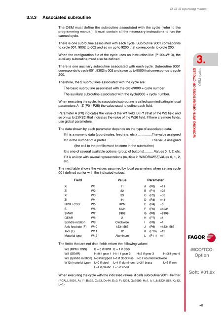
The next table shows the values assumed by local parameters when setting cycle<br />
001 defined earlier with the indicated values.<br />
Field Value Parameter<br />
Xi W1 11 A (P0) =11<br />
Zi W2 22 B (P1) =22<br />
Xf W3 33 C (P2) =33<br />
Zf W4 44 D (P3) =44<br />
RPM / CSS W5 RPM E (P4) =0<br />
S W6 1234 F (P5) =1234<br />
SMAX W7 9999 G (P6) =9999<br />
GEAR W8 2 H (P7) =1<br />
Spindle rotation W9 Clockwise I (P8) =1<br />
Axis feedrate (F) W10 1234.567 J (P9) =1234.567<br />
Tool (T) W11 12 K (P10) =12<br />
Material type W12 Aluminum L (P11) =1<br />
The fields that are not data fields return the following values:<br />
W5 (RPM / CSS) E = 0 if RPM E = 1 if CSS<br />
W8 (GEAR) H=0 if gear 1 H=1 if gear 2 H=2 if gear 3 H=3 if gear 4<br />
W9 (spindle rotation) I=0 if stopped I=1 if clockwise I=2 if counterclockwise<br />
W12 (material type) L=0 if steel L=1 if aluminum L=2 if brass L=3 if iron<br />
L=4 if plastic L=5 if wood<br />
When executing the cycle with the indicated values, it calls subroutine 9001 like this:<br />
(PCALL 9001, A=11, B=22, C=33, D=44, E=0, F=1234, G=9999, H=1, I=1, J=1234.567, K=12,<br />
L=1)<br />
Operating <strong>man</strong>ual<br />
WORKING WITH OPERATIONS OR CYCLES<br />
OEM cycles 3.<br />
·MCO/TCO·<br />
Option<br />
Soft: V01.0x<br />
·41·


