

LANTEK User Manual - Ideal Industries
LANTEK User Manual - Ideal Industries
LANTEK User Manual - Ideal Industries

Create successful ePaper yourself
Turn your PDF publications into a flip-book with our unique Google optimized e-Paper software.
Chapter 6<br />
Fiber Optics Diagnostics (TRACETEK)<br />
TRACETEK works by launching a high-power laser pulse down the fiber and monitoring<br />
reflections returned by the end of the cable, connectors, mechanical splices, and cable<br />
breaks. This important functionality will help locate sources of excessive reflection in<br />
the cabling system. Excessive reflection in an optical system leads to high bit error<br />
rates, preventing the network from operating at its full capability.<br />
One of the most common sources of excessive return loss is dirty or poorly polished<br />
connectors. When there is too much reflection in a system, the reflected power can<br />
interact with the downstream signal, either increasing or decreasing the amplitude of<br />
the transmitted signal. Additionally, if the reflection is strong enough it can interfere<br />
with the feedback circuit on the laser transmitter causing fluctuations in output power.<br />
Unlike a power meter, which measures the loss across a link, TRACETEK displays the<br />
relative reflection of events in a link allowing the user to isolate and remedy problems.<br />
TRACETEK DISPLAY<br />
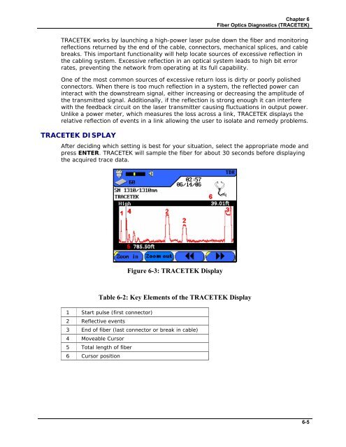
After deciding which setting is best for your situation, select the appropriate mode and<br />
press ENTER. TRACETEK will sample the fiber for about 30 seconds before displaying<br />
the acquired trace data.<br />
Figure 6-3: TRACETEK Display<br />
Table 6-2: Key Elements of the TRACETEK Display<br />
1 Start pulse (first connector)<br />
2 Reflective events<br />
3 End of fiber (last connector or break in cable)<br />
4 Moveable Cursor<br />
5 Total length of fiber<br />
6 Cursor position<br />
6-5


