

LANTEK User Manual - Ideal Industries
LANTEK User Manual - Ideal Industries
LANTEK User Manual - Ideal Industries

You also want an ePaper? Increase the reach of your titles
YUMPU automatically turns print PDFs into web optimized ePapers that Google loves.
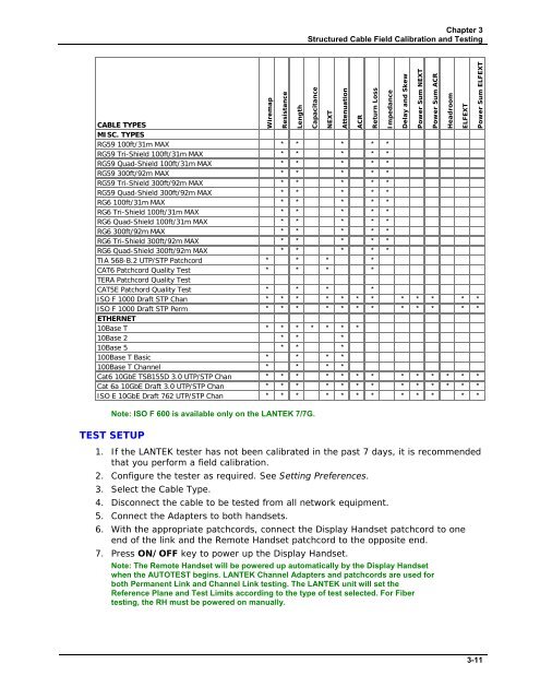
Chapter 3<br />
Structured Cable Field Calibration and Testing<br />
Wiremap<br />
Resistance<br />
CABLE TYPES<br />
MISC. TYPES<br />
RG59 100ft/31m MAX * * * * *<br />
RG59 Tri-Shield 100ft/31m MAX * * * * *<br />
RG59 Quad-Shield 100ft/31m MAX * * * * *<br />
RG59 300ft/92m MAX * * * * *<br />
RG59 Tri-Shield 300ft/92m MAX * * * * *<br />
RG59 Quad-Shield 300ft/92m MAX * * * * *<br />
RG6 100ft/31m MAX * * * * *<br />
RG6 Tri-Shield 100ft/31m MAX * * * * *<br />
RG6 Quad-Shield 100ft/31m MAX * * * * *<br />
RG6 300ft/92m MAX * * * * *<br />
RG6 Tri-Shield 300ft/92m MAX * * * * *<br />
RG6 Quad-Shield 300ft/92m MAX * * * * *<br />
TIA 568-B.2 UTP/STP Patchcord * * * *<br />
CAT6 Patchcord Quality Test * * * *<br />
TERA Patchcord Quality Test<br />
CAT5E Patchord Quality Test * * * *<br />
ISO F 1000 Draft STP Chan * * * * * * * * * * * *<br />
ISO F 1000 Draft STP Perm * * * * * * * * * * * *<br />
ETHERNET<br />
10Base T * * * * * * *<br />
10Base 2 * * *<br />
10Base 5 * * *<br />
100Base T Basic * * * *<br />
100Base T Channel * * * *<br />
Cat6 10GbE TSB155D 3.0 UTP/STP Chan * * * * * * * * * * * * *<br />
Cat 6a 10GbE Draft 3.0 UTP/STP Chan * * * * * * * * * * * * *<br />
ISO E 10GbE Draft 762 UTP/STP Chan * * * * * * * * * * * *<br />
Note: ISO F 600 is available only on the <strong>LANTEK</strong> 7/7G.<br />
TEST SETUP<br />
1. If the <strong>LANTEK</strong> tester has not been calibrated in the past 7 days, it is recommended<br />
that you perform a field calibration.<br />
2. Configure the tester as required. See Setting Preferences.<br />
3. Select the Cable Type.<br />
4. Disconnect the cable to be tested from all network equipment.<br />
5. Connect the Adapters to both handsets.<br />
6. With the appropriate patchcords, connect the Display Handset patchcord to one<br />
end of the link and the Remote Handset patchcord to the opposite end.<br />
7. Press ON/OFF key to power up the Display Handset.<br />
Note: The Remote Handset will be powered up automatically by the Display Handset<br />
when the AUTOTEST begins. <strong>LANTEK</strong> Channel Adapters and patchcords are used for<br />
both Permanent Link and Channel Link testing. The <strong>LANTEK</strong> unit will set the<br />
Reference Plane and Test Limits according to the type of test selected. For Fiber<br />
testing, the RH must be powered on manually.<br />
Length<br />
Capacitance<br />
NEXT<br />
Attenuation<br />
ACR<br />
Return Loss<br />
Impedance<br />
Delay and Skew<br />
Power Sum NEXT<br />
Power Sum ACR<br />
Headroom<br />
ELFEXT<br />
Power Sum ELFEXT<br />
3-11


