

LANTEK User Manual - Ideal Industries
LANTEK User Manual - Ideal Industries
LANTEK User Manual - Ideal Industries

Create successful ePaper yourself
Turn your PDF publications into a flip-book with our unique Google optimized e-Paper software.
Chapter 5<br />
Fiber Optics Cable Field Calibration and Testing<br />
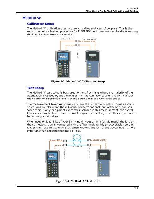
METHOD ‘A’<br />
Calibration Setup<br />
The Method ‘A’ calibration uses two launch cables and a set of couplers. This is the<br />
recommended calibration procedure for FIBERTEK, as it does not require disconnecting<br />
the launch cables from the modules.<br />
Test Setup<br />
Figure 5-3: Method 'A' Calibration Setup<br />
The Method ‘A’ test setup is best used for long fiber links where the majority of the<br />
attenuation is caused by the cable itself, not the connectors. With this configuration,<br />
the calibration reference plane is at the patch panel and work area outlet.<br />
The measurement taken will include the loss of the fiber optic cable (including inline<br />
splices and couplers) and the individual connector at each end of the link (one pair).<br />
Since there is only one pair of connectors included in this measurement, the overall<br />
loss values may be lower than one would expect, particularly when this setup is used<br />
to test very short cables.<br />
When used on long links of over 1km (multimode) or 4km (single mode) the loss of<br />
the connectors is small compared with the fiber, making this an acceptable setup for<br />
longer links. Use this configuration when knowing the loss of the optical fiber is more<br />
important than knowing the total link loss.<br />
Figure 5-4: Method ‘A’ Test Setup<br />
5-5


