

LANTEK User Manual - Ideal Industries
LANTEK User Manual - Ideal Industries
LANTEK User Manual - Ideal Industries

Create successful ePaper yourself
Turn your PDF publications into a flip-book with our unique Google optimized e-Paper software.
Chapter 3<br />
Structured Cable Field Calibration and Testing<br />
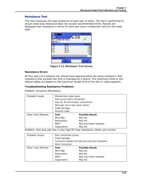
Resistance Test<br />
This test measures the loop resistance of each pair of wires. The test is performed to<br />
ensure total loop resistance does not exceed recommended limits. Results are<br />
displayed with resistance in ohms for each pair and a comparison limit for the cable<br />
type.<br />
Resistance Errors<br />
Figure 3-12: Resistance Test Screen<br />
All four pairs of a network link should have approximately the same resistance. Pair<br />
resistance that exceeds the limit is indicated as a failure. The maximum limits in the<br />
default tables are based on the maximum length limit of the link or cable segment.<br />
Troubleshooting Resistance Problems<br />
Problem: Excessive Resistance<br />
Probable Causes<br />
Mismatched cable types.<br />
Poor punch block connection.<br />
Poor RJ-45 termination connections.<br />
Wire pair has a tap (never done).<br />
Cable damage.<br />
Shorted cable.<br />
Other Tests Affected Test Possible Result<br />
Wire Map<br />
May fail.<br />
Attenuation<br />
May fail.<br />
NEXT<br />
May have false readings.<br />
Capacitance<br />
May fail.<br />
Problem: One wire pair has a very high DC loop resistance, others are normal.<br />
Probable Causes<br />
Poor connection points.<br />
Cable damage.<br />
Connector blades not fully piercing wire insulation.<br />
Worn Connector<br />
Other Tests Affected Test Possible Result<br />
Wire Map<br />
May fail.<br />
Attenuation<br />
May fail.<br />
NEXT<br />
May have false readings.<br />
Capacitance<br />
May fail.<br />
3-23


