ECK-3699GF Embedded System User Manual - ICP America
ECK-3699GF Embedded System User Manual - ICP America
ECK-3699GF Embedded System User Manual - ICP America
Create successful ePaper yourself
Turn your PDF publications into a flip-book with our unique Google optimized e-Paper software.
<strong>ECK</strong>-<strong>3699GF</strong> <strong>Embedded</strong> <strong>System</strong><br />
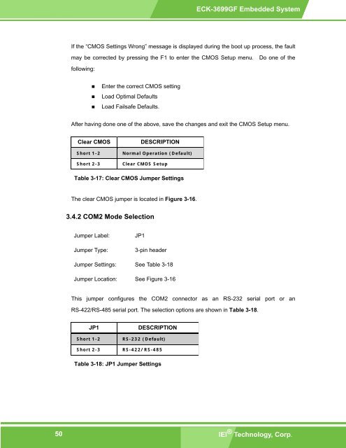
If the “CMOS Settings Wrong” message is displayed during the boot up process, the fault<br />
may be corrected by pressing the F1 to enter the CMOS Setup menu. Do one of the<br />
following:<br />
• Enter the correct CMOS setting<br />
• Load Optimal Defaults<br />
• Load Failsafe Defaults.<br />
After having done one of the above, save the changes and exit the CMOS Setup menu.<br />
Clear CMOS<br />
Short 1-2<br />
Short 2-3<br />
DESCRIPTION<br />
Normal Operation (Default)<br />
Clear CMOS Setup<br />
Table 3-17: Clear CMOS Jumper Settings<br />
The clear CMOS jumper is located in Figure 3-16.<br />
3.4.2 COM2 Mode Selection<br />
Jumper Label:<br />
Jumper Type:<br />
JP1<br />
3-pin header<br />
Jumper Settings: See Table 3-18<br />
Jumper Location: See Figure 3-16<br />
This jumper configures the COM2 connector as an RS-232 serial port or an<br />
RS-422/RS-485 serial port. The selection options are shown in Table 3-18.<br />
JP1<br />
Short 1-2<br />
Short 2-3<br />
DESCRIPTION<br />
RS-232 (Default)<br />
RS-422/RS-485<br />
Table 3-18: JP1 Jumper Settings<br />
50<br />
IEI ® Technology, Corp.


