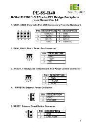
ECK-3699GF Embedded System User Manual - ICP America
ECK-3699GF Embedded System User Manual - ICP America
ECK-3699GF Embedded System User Manual - ICP America

You also want an ePaper? Increase the reach of your titles
YUMPU automatically turns print PDFs into web optimized ePapers that Google loves.
<strong>ECK</strong>-<strong>3699GF</strong> <strong>Embedded</strong> <strong>System</strong><br />
Output Power 4-pin header PW1<br />
Table 3-20: Power Module Connector Pinouts<br />
Figure 3-17: Power Module Connector Locations<br />
The pin outs for these connectors are listed in the sections below.<br />
3.5.1 Input Power Connector<br />
The input power connector, CN1, is connected directly to the rear panel power socket.<br />
Power is received in this connector from an external power source and fed into the<br />
system.<br />
PIN NO.<br />
Description<br />
1 Vin<br />
2 Vin<br />
3 GND<br />
Table 3-21: Input Power Connector Pinouts<br />
3.5.2 Output Power Connector [Motherboard]<br />
The 20-pin output power connector, PW2, is connected directly to the main power<br />
connector on the KINO series motherboard.<br />
52<br />
IEI ® Technology, Corp.