

Application Note AN-1150 - International Rectifier
Application Note AN-1150 - International Rectifier
Application Note AN-1150 - International Rectifier

Create successful ePaper yourself
Turn your PDF publications into a flip-book with our unique Google optimized e-Paper software.
I<br />
− .75V<br />
PK _ LMT<br />
= = 15<br />
0.05Ω<br />
It is clarified that even though the IR1152 operates based on average current<br />
mode control, the input to the peak current limit comparator is decoupled from<br />
the averaging circuit thus enabling instantaneous cycle-by-cycle protection for<br />
peak overcurrent.<br />
A<br />
R BOP2<br />
R BOP3<br />
IR1152<br />
IR1145<br />
C BOP R gm 1<br />
COM<br />
2<br />
COMP<br />
3<br />
ISNS<br />
4<br />
BOP<br />
C P<br />
C C Z SF R SF<br />
COM<br />
GATE 8<br />
VCC 7<br />
VFB 6<br />
OVP/EN 5<br />
R<br />
V<br />
C VCC<br />
R SNS<br />
GND<br />
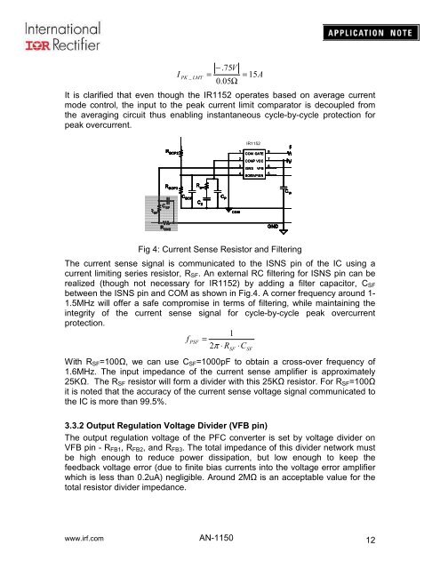
Fig 4: Current Sense Resistor and Filtering<br />
The current sense signal is communicated to the ISNS pin of the IC using a<br />
current limiting series resistor, R SF . An external RC filtering for ISNS pin can be<br />
realized (though not necessary for IR1152) by adding a filter capacitor, C SF<br />
between the ISNS pin and COM as shown in Fig.4. A corner frequency around 1-<br />
1.5MHz will offer a safe compromise in terms of filtering, while maintaining the<br />
integrity of the current sense signal for cycle-by-cycle peak overcurrent<br />
protection.<br />
1<br />
f<br />
PSF<br />
= 2π ⋅ R ⋅C<br />
With R SF =100Ω, we can use C SF =1000pF to obtain a cross-over frequency of<br />
1.6MHz. The input impedance of the current sense amplifier is approximately<br />
25KΩ. The R SF resistor will form a divider with this 25KΩ resistor. For R SF =100Ω<br />
it is noted that the accuracy of the current sense voltage signal communicated to<br />
the IC is more than 99.5%.<br />
3.3.2 Output Regulation Voltage Divider (VFB pin)<br />
The output regulation voltage of the PFC converter is set by voltage divider on<br />
VFB pin - R FB1 , R FB2 , and R FB3 . The total impedance of this divider network must<br />
be high enough to reduce power dissipation, but low enough to keep the<br />
feedback voltage error (due to finite bias currents into the voltage error amplifier<br />
which is less than 0.2uA) negligible. Around 2MΩ is an acceptable value for the<br />
total resistor divider impedance.<br />
SF<br />
SF<br />
www.irf.com <strong>AN</strong>-<strong>1150</strong><br />
12


