

Application Note AN-1150 - International Rectifier
Application Note AN-1150 - International Rectifier
Application Note AN-1150 - International Rectifier

You also want an ePaper? Increase the reach of your titles
YUMPU automatically turns print PDFs into web optimized ePapers that Google loves.
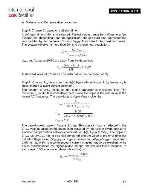
Voltage Loop Compensation procedure<br />
Step 1: Choose C z based on soft-start time:<br />
A soft-start time of 60ms is selected. Typical values range from 50ms to a few<br />
hundred ms, depending upon the application. The soft-start time represents the<br />
time needed by the controller to ramp V COMP from zero to the maximum value.<br />
The system will take no more than 60ms to achieve near-regulation.<br />
C<br />
Z<br />
=<br />
V<br />
t<br />
COMP<br />
SS<br />
⋅ i<br />
OVEA<br />
( EFF )( MIN )<br />
i OVEA and V COMP(EFF) (MIN) are taken from the datasheet.<br />
60ms<br />
× 44µ<br />
A<br />
C Z<br />
=<br />
= 0.56µ<br />
F<br />
4.7V<br />
A standard value of 0.56uF can be selected for the converter for C Z .<br />
Step 2: Choose R gm to ensure that H 1 (s).H 2 (s) attenuation at 2xf AC frequency is<br />
small enough to avoid current distortion:<br />
The amount of 2xf AC ripple on the output capacitor is calculated first. The<br />
minimum f AC of 47Hz is considered here, since the ripple is the maximum at the<br />
lowest AC frequency. The peak-to-zero ripple V OPK is given by:<br />
V<br />
V<br />
V<br />
OPK<br />
OPK<br />
OPK<br />
P<br />
=<br />
2π<br />
⋅ 2 ⋅ f<br />
= 5.1V<br />
in,<br />
MAX<br />
AC<br />
⋅ C<br />
O<br />
⋅V<br />
out<br />
380W<br />
=<br />
2π<br />
⋅ 2 ⋅ 47 ⋅ 330µ<br />
F ⋅385V<br />
The peak-to-peak ripple in V OUT is 2xV OPK . This ripple in V OUT is reflected in the<br />
V COMP voltage based on the attenuation provided by the resistor divider and error<br />
amplifier compensation network combined i.e. H 1 (s).H 2 (s) at 2xf AC . The ripple in<br />
V COMP i.e. ∆V COMP has to be small compared with the value of the error amplifier<br />
output voltage swing (V COMP,EFF ). Typical values for ∆V COMP /V COMP range from<br />
0.5% to 1%. 0.5% is recommended if current shaping has to be excellent while<br />
1% is recommended for higher phase margin and low-oscillation response to<br />
load steps. 0.5% attenuation demands a (G VA ) of:<br />
G<br />
VA<br />
V<br />
=<br />
COMP(<br />
EFF )<br />
2 ⋅V<br />
⋅ 0.005<br />
OPK<br />
www.irf.com <strong>AN</strong>-<strong>1150</strong><br />
23


