

Application Note AN-1150 - International Rectifier
Application Note AN-1150 - International Rectifier
Application Note AN-1150 - International Rectifier

You also want an ePaper? Increase the reach of your titles
YUMPU automatically turns print PDFs into web optimized ePapers that Google loves.
1<br />
1<br />
f<br />
P0<br />
=<br />
≅<br />
Cz ⋅Cp<br />
2π<br />
⋅ R<br />
2π<br />
⋅ Rgm<br />
⋅Cp<br />
gm<br />
Cz + Cp<br />
C = 1<br />
= 7. nF<br />
p<br />
2 ⋅ 2kΩ ⋅ 66kHz<br />
⋅ 0.166<br />
32<br />
π<br />
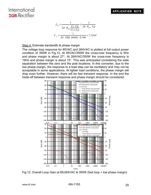
Step 4: Estimate bandwidth & phase margin<br />
The voltage loop response for 85VAC and 264VAC is plotted at full output power<br />
condition of 350W in Fig.12. At 85VAC/350W the cross-over frequency is 5Hz<br />
and phase margin is about 27°. At 264VAC/350W the cross-over frequency is<br />
16Hz and phase margin is about 15°. This was anticipated considering the wide<br />
separation between the zero and the pole locations. In this converter, due to the<br />
low phase margin, the response to a load step can be oscillatory and may not be<br />
acceptable in some applications. At lighter load conditions, the phase margin will<br />
drop even further. However, there will be fast transient response. In the end the<br />
trade-off between transient response and phase margin should be considered.<br />
90<br />
60<br />
30<br />
0<br />
Gain 85VAC Uncompensated<br />
Gain 85VAC Compensated<br />
EA Gain<br />
Phase 85VAC Uncompensated<br />
Phase 85VAC Compensated<br />
EA Phase<br />
90<br />
60<br />
30<br />
0<br />
Gain (dB)<br />
-30<br />
-60<br />
-90<br />
-120<br />
-150<br />
-30<br />
-60<br />
-90<br />
-120<br />
-150<br />
Phase (deg)<br />
-180<br />
-180<br />
0.01<br />
90<br />
0.1 1 10 100 1000 10000 100000<br />
90<br />
f (Hz) Gain 264VAC Uncompensated<br />
60<br />
Gain 264VAC Compensated<br />
60<br />
EA Gain<br />
30<br />
EA Phase<br />
Phase 264VAC Uncompensated<br />
30<br />
Phase 264VAC Compensated<br />
0<br />
0<br />
Gain (dB)<br />
-30<br />
-60<br />
-90<br />
-120<br />
-150<br />
-30<br />
-60<br />
-90<br />
-120<br />
-150<br />
Phase (deg)<br />
-180<br />
-180<br />
0.01 0.1 1 10 100 1000 10000 100000<br />
f (Hz)<br />
Fig.12: Overall Loop Gain at 85/264VAC & 350W (fast loop + low phase margin)<br />
www.irf.com <strong>AN</strong>-<strong>1150</strong><br />
25


