

Application Note AN-1150 - International Rectifier
Application Note AN-1150 - International Rectifier
Application Note AN-1150 - International Rectifier

Create successful ePaper yourself
Turn your PDF publications into a flip-book with our unique Google optimized e-Paper software.
Phase Margin Discussion:<br />
The zero in the error amplifier compensation can provide phase boost to<br />
compensate the phase lag due to the power stage pole. If the zero is more than a<br />
decade away from the power stage pole there is minimal phase boost. The<br />
location of the zero can be brought closer to the power stage pole by increasing<br />
the value of C z or R gm or both. However, the trade-offs are as follows:<br />
• Increasing C z reduces the DC gain of the transfer function and slows<br />
down the loop response (more sluggish response to a load step)<br />
• Increasing R gm increases the low frequency gain of the error amplifier<br />
transfer function and hence the attenuation at 2xf AC may be insufficient to<br />
meet the 0.5% requirement described earlier.<br />
To illustrate the trade-offs, the following examples are presented with the goal of<br />
improving the phase margin:<br />
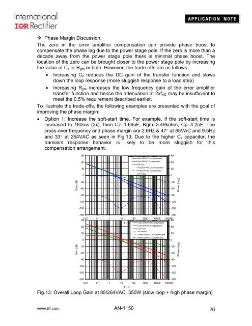
• Option 1: Increase the soft-start time. For example, if the soft-start time is<br />
increased to 180ms (3x), then Cz=1.69uF, Rgm=3.49kohm, Cp=4.2nF. The<br />
cross-over frequency and phase margin are 2.6Hz & 47° at 85VAC and 9.5Hz<br />
and 33° at 264VAC as seen in Fig.13. Due to the higher C z capacitor, the<br />
transient response behavior is likely to be more sluggish for this<br />
compensation arrangement.<br />
90<br />
60<br />
30<br />
0<br />
Gain 85VAC Uncompensated<br />
Gain 85VAC Compensated<br />
EA Gain<br />
Phase 85VAC Uncompensated<br />
Phase 85VAC Compensated<br />
EA Phase<br />
90<br />
60<br />
30<br />
0<br />
Gain (dB)<br />
-30<br />
-60<br />
-90<br />
-120<br />
-150<br />
-30<br />
-60<br />
-90<br />
-120<br />
-150<br />
Phase (deg)<br />
-180<br />
-180<br />
0.01<br />
90<br />
0.1 1 10 100 1000 10000 100000<br />
90<br />
f (Hz) Gain 264VAC Uncompensated<br />
60<br />
Gain 264VAC Compensated<br />
60<br />
EA Gain<br />
30<br />
EA Phase<br />
Phase 264VAC Uncompensated<br />
30<br />
Phase 264VAC Compensated<br />
0<br />
0<br />
Gain (dB)<br />
-30<br />
-60<br />
-90<br />
-120<br />
-150<br />
-30<br />
-60<br />
-90<br />
-120<br />
-150<br />
Phase (deg)<br />
-180<br />
-180<br />
0.01 0.1 1 10 100 1000 10000 100000<br />
f (Hz)<br />
Fig.13: Overall Loop Gain at 85/264VAC, 350W (slow loop + high phase margin)<br />
www.irf.com <strong>AN</strong>-<strong>1150</strong><br />
26


