

Application Note AN-1150 - International Rectifier
Application Note AN-1150 - International Rectifier
Application Note AN-1150 - International Rectifier

You also want an ePaper? Increase the reach of your titles
YUMPU automatically turns print PDFs into web optimized ePapers that Google loves.
• Option 3: This is the compromise approach between option 1 & 2 and is left to<br />
the user to pursue (for example using soft-start time=100ms & H1(s).H2(s)<br />
attenuation at 2xf AC = 1%).<br />
4. PFC Converter Physical Design & Layout Tips<br />
4.1 Pin COM<br />
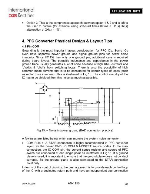
Grounding is the most important layout consideration for PFC ICs. Some ICs<br />
even have separate power ground and signal ground pins for better noise<br />
immunity. Since IR1152 has only one ground pin, additional care is required<br />
during board layout. The parasitic inductance and capacitance in the power<br />
ground trace usually generates a lot of noise because of high RMS currents and<br />
‘dV/dt’s & ‘dI/dt’s from switching loops. There is also the possibility of high<br />
common-mode currents that is to be considered for certain types of loads (such<br />
as motor drive inverters). This is illustrated in Fig.15. The control circuitry of the<br />
IC has to be shielded from this noise as much as possible.<br />
- +<br />
1<br />
2<br />
3<br />
4<br />
COM GATE 8<br />
COMP VCC 7<br />
ISNS VFB 6<br />
BOPOVP/EN 5<br />
These traces carry high frequency current<br />
Easy to generate noise with parasitic inductance<br />
Fig.15: – Noise in power ground (BAD connection practice)<br />
A few rules are listed below which can improve the system noise immunity.<br />
• COM Rule 1: A STAR-connection is highly recommended in PFC converter<br />
layout for the power GND, IC COM & MOSFET source nodes. In the starconnection,<br />
the IC COM pin, the current sense resistor and source of PFC<br />
switch are connected at one single point as illustrated in Fig.16. If a ground<br />
plane is used, it is important to ensure that the ground plane does not conduct<br />
currents. So the ground plane is also connected to the STAR-connection<br />
point only.<br />
In terms of the control circuitry, the best approach is to provide each control loop<br />
of the IC with a dedicated return path and have an independent star-connection<br />
www.irf.com <strong>AN</strong>-<strong>1150</strong><br />
28


