

Application Note AN-1150 - International Rectifier
Application Note AN-1150 - International Rectifier
Application Note AN-1150 - International Rectifier

Create successful ePaper yourself
Turn your PDF publications into a flip-book with our unique Google optimized e-Paper software.
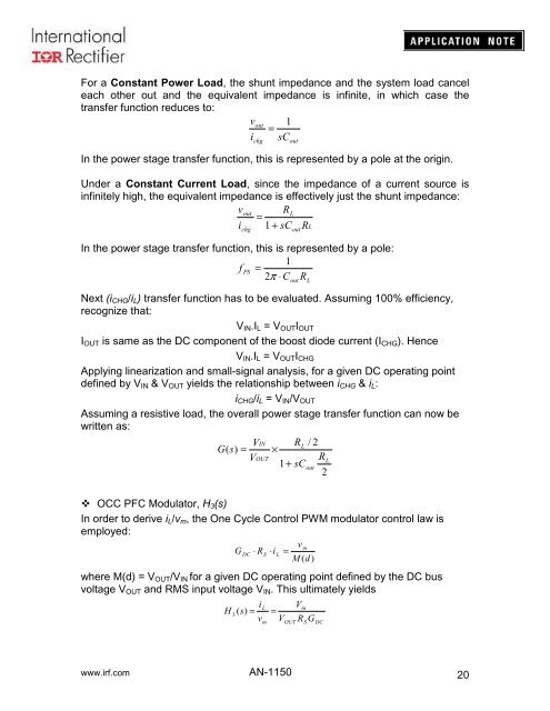
For a Constant Power Load, the shunt impedance and the system load cancel<br />
each other out and the equivalent impedance is infinite, in which case the<br />
transfer function reduces to:<br />
vout<br />
1<br />
=<br />
i sC<br />
chg<br />
In the power stage transfer function, this is represented by a pole at the origin.<br />
Under a Constant Current Load, since the impedance of a current source is<br />
infinitely high, the equivalent impedance is effectively just the shunt impedance:<br />
vout<br />
RL<br />
=<br />
i 1 + sC RL<br />
In the power stage transfer function, this is represented by a pole:<br />
1<br />
f<br />
PS<br />
= 2π<br />
⋅C<br />
R<br />
chg<br />
Next (i CHG /i L ) transfer function has to be evaluated. Assuming 100% efficiency,<br />
recognize that:<br />
V IN .I L = V OUT I OUT<br />
I OUT is same as the DC component of the boost diode current (I CHG ). Hence<br />
V IN .I L = V OUT I CHG<br />
Applying linearization and small-signal analysis, for a given DC operating point<br />
defined by V IN & V OUT yields the relationship between i CHG & i L :<br />
i CHG /i L = V IN /V OUT<br />
Assuming a resistive load, the overall power stage transfer function can now be<br />
written as:<br />
V<br />
G(<br />
s)<br />
=<br />
V<br />
IN<br />
OUT<br />
out<br />
out<br />
out<br />
RL<br />
×<br />
1+<br />
sC<br />
L<br />
/ 2<br />
out<br />
R<br />
2<br />
L<br />
OCC PFC Modulator, H 3 (s)<br />
In order to derive i L /v m , the One Cycle Control PWM modulator control law is<br />
employed:<br />
v<br />
m<br />
G<br />
DC<br />
⋅ RS<br />
⋅iL<br />
=<br />
M (d)<br />
where M(d) = V OUT /V IN for a given DC operating point defined by the DC bus<br />
voltage V OUT and RMS input voltage V IN . This ultimately yields<br />
L<br />
H<br />
3<br />
( s)<br />
= =<br />
vm<br />
i<br />
V<br />
OUT<br />
V<br />
R<br />
in<br />
S<br />
G<br />
DC<br />
www.irf.com <strong>AN</strong>-<strong>1150</strong><br />
20


