

Application Note AN-1150 - International Rectifier
Application Note AN-1150 - International Rectifier
Application Note AN-1150 - International Rectifier

You also want an ePaper? Increase the reach of your titles
YUMPU automatically turns print PDFs into web optimized ePapers that Google loves.
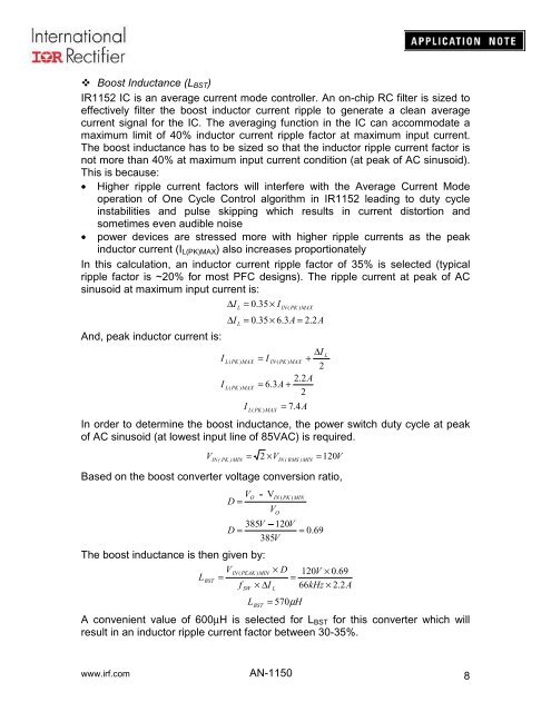
Boost Inductance (L BST )<br />
IR1152 IC is an average current mode controller. An on-chip RC filter is sized to<br />
effectively filter the boost inductor current ripple to generate a clean average<br />
current signal for the IC. The averaging function in the IC can accommodate a<br />
maximum limit of 40% inductor current ripple factor at maximum input current.<br />
The boost inductance has to be sized so that the inductor ripple current factor is<br />
not more than 40% at maximum input current condition (at peak of AC sinusoid).<br />
This is because:<br />
• Higher ripple current factors will interfere with the Average Current Mode<br />
operation of One Cycle Control algorithm in IR1152 leading to duty cycle<br />
instabilities and pulse skipping which results in current distortion and<br />
sometimes even audible noise<br />
• power devices are stressed more with higher ripple currents as the peak<br />
inductor current (I L(PK)MAX ) also increases proportionately<br />
In this calculation, an inductor current ripple factor of 35% is selected (typical<br />
ripple factor is ~20% for most PFC designs). The ripple current at peak of AC<br />
sinusoid at maximum input current is:<br />
∆I<br />
= .35×<br />
I<br />
And, peak inductor current is:<br />
I<br />
I<br />
∆I<br />
L<br />
L<br />
L(<br />
PK ) MAX<br />
L(<br />
PK ) MAX<br />
0<br />
IN ( PK ) MAX<br />
= 0.35×<br />
6.3A<br />
= 2.2A<br />
I<br />
∆I<br />
= I<br />
IN ( PK ) MAX<br />
+<br />
2<br />
2.2A<br />
= 6.3A<br />
+<br />
2<br />
L( PK ) MAX<br />
= 7. 4<br />
In order to determine the boost inductance, the power switch duty cycle at peak<br />
of AC sinusoid (at lowest input line of 85VAC) is required.<br />
VIN ( PK )MIN<br />
= 2 × VIN(<br />
RMS ) MIN<br />
= 120V<br />
Based on the boost converter voltage conversion ratio,<br />
V<br />
D =<br />
O<br />
385V<br />
− 120V<br />
D =<br />
385V<br />
A<br />
V<br />
IN ( PK ) MIN<br />
V<br />
O<br />
= 0.69<br />
The boost inductance is then given by:<br />
VIN<br />
( PEAK ) MIN<br />
× D 120V<br />
× 0.69<br />
LBST<br />
=<br />
=<br />
f × ∆I<br />
66kHz<br />
× 2.2A<br />
SW<br />
L<br />
L BST<br />
= 570µH<br />
A convenient value of 600µH is selected for L BST for this converter which will<br />
result in an inductor ripple current factor between 30-35%.<br />
L<br />
www.irf.com <strong>AN</strong>-<strong>1150</strong><br />
8


