

Application Note AN-1150 - International Rectifier
Application Note AN-1150 - International Rectifier
Application Note AN-1150 - International Rectifier

You also want an ePaper? Increase the reach of your titles
YUMPU automatically turns print PDFs into web optimized ePapers that Google loves.
as mentioned earlier, for the PFC converter, the most important criterion for<br />
basing the selection of the compensation component values is the voltage loop<br />
bandwidth.<br />
Fig10: Voltage Loop error amplifier compensation network<br />
The error amplifier transfer function is given by:<br />
gm<br />
⋅(<br />
1+<br />
sRgmCZ<br />
)<br />
H<br />
2<br />
( s ) =<br />
s( C + C + sR C C<br />
Z<br />
where g m is the transconductance of the voltage error amplifier. The<br />
compensation network adds a zero and a pole in the transfer function at:<br />
f<br />
f<br />
P0<br />
Z 0<br />
= π ⋅<br />
P<br />
1<br />
2 R<br />
=<br />
2π ⋅ R<br />
gm<br />
⋅ C<br />
gm<br />
Z<br />
1<br />
Cz ⋅Cp<br />
Cz + Cp<br />
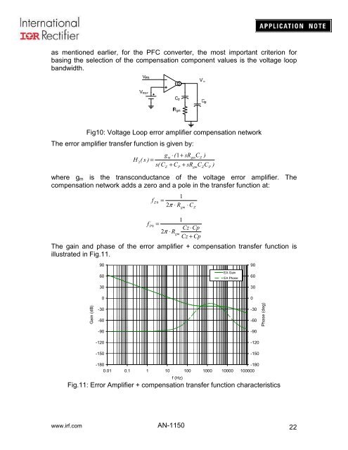
The gain and phase of the error amplifier + compensation transfer function is<br />
illustrated in Fig.11.<br />
gm<br />
Z<br />
P<br />
)<br />
90<br />
60<br />
30<br />
0<br />
EA Gain<br />
EA Phase<br />
90<br />
60<br />
30<br />
0<br />
Gain (dB)<br />
-30<br />
-60<br />
-90<br />
-120<br />
-150<br />
-30<br />
-60<br />
-90<br />
-120<br />
-150<br />
Phase (deg)<br />
-180<br />
-180<br />
0.01 0.1 1 10 100 1000 10000 100000<br />
f (Hz)<br />
Fig.11: Error Amplifier + compensation transfer function characteristics<br />
www.irf.com <strong>AN</strong>-<strong>1150</strong><br />
22


