

Application Note AN-1150 - International Rectifier
Application Note AN-1150 - International Rectifier
Application Note AN-1150 - International Rectifier

Create successful ePaper yourself
Turn your PDF publications into a flip-book with our unique Google optimized e-Paper software.
G<br />
G<br />
VA<br />
VA<br />
4.7V<br />
⋅ 0.005<br />
=<br />
= 0.0023<br />
2 ⋅5.1V<br />
= −52.7dB<br />
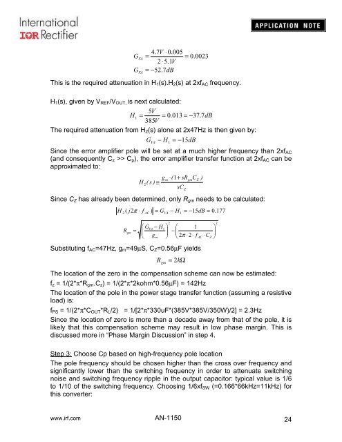
This is the required attenuation in H 1 (s).H 2 (s) at 2xf AC frequency.<br />
H 1 (s), given by V REF /V OUT, is next calculated:<br />
5V<br />
H1 = = 0.013 = −37.<br />
7dB<br />
385V<br />
The required attenuation from H 2 (s) alone at 2x47Hz is then given by:<br />
G VA<br />
− H = 15dB<br />
1<br />
−<br />
Since the error amplifier pole will be set at a much higher frequency than 2xf AC<br />
(and consequently C z >> C p ), the error amplifier transfer function at 2xf AC can be<br />
approximated to:<br />
H<br />
2<br />
(<br />
s )<br />
g<br />
≅<br />
m<br />
⋅(<br />
1+<br />
sR<br />
Since C Z has already been determined, only R gm needs to be calculated:<br />
sC<br />
H<br />
2<br />
( j2π<br />
⋅ f<br />
AC<br />
) = GVA<br />
− H<br />
1<br />
= −15dB<br />
= 0.177<br />
R<br />
gm<br />
=<br />
⎛ G<br />
⎜<br />
⎝<br />
VA<br />
− H<br />
g<br />
m<br />
1<br />
2<br />
Z<br />
gm<br />
C<br />
Z<br />
⎞ ⎛ 1<br />
⎟ −<br />
⎜<br />
⎠ ⎝ 2π<br />
⋅ 2 ⋅ f<br />
Substituting f AC =47Hz, g m =49µS, C Z =0.56µF yields<br />
R gm<br />
= 2 kΩ<br />
The location of the zero in the compensation scheme can now be estimated:<br />
f z = 1/(2*π*R gm .C z ) = 1/(2*π*2kohm*0.56µF) = 142Hz<br />
The location of the pole in the power stage transfer function (assuming a resistive<br />
load) is:<br />
f PS = 1/(2*π*C OUT *R L /2) = 1/[2*π*330uF*(385V*385V/350W)/2] = 2.3Hz<br />
Since the location of zero is more than a decade away from that of the pole, it is<br />
likely that this compensation scheme may result in low phase margin. This is<br />
discussed more in “Phase Margin Discussion” in step 4.<br />
Step 3: Choose Cp based on high-frequency pole location<br />
The pole frequency should be chosen higher than the cross over frequency and<br />
significantly lower than the switching frequency in order to attenuate switching<br />
noise and switching frequency ripple in the output capacitor: typical value is 1/6<br />
to 1/10 of the switching frequency. Choosing 1/6xf SW (=0.166*66kHz=11kHz) for<br />
this converter:<br />
)<br />
AC<br />
⋅C<br />
Z<br />
2<br />
⎞<br />
⎟<br />
⎠<br />
www.irf.com <strong>AN</strong>-<strong>1150</strong><br />
24


