Application Note AN-1150 - International Rectifier
Application Note AN-1150 - International Rectifier
Application Note AN-1150 - International Rectifier
Create successful ePaper yourself
Turn your PDF publications into a flip-book with our unique Google optimized e-Paper software.
∆V BOP magnitude is related to C BOP – bigger the capacitor, smaller the ripple.<br />
During start-up, the IC is held in Stand-by mode when the BOP pin voltage, V BOP<br />
is less than V BOP(EN) =1.56V. Next, when the AC voltage is applied and the BOP<br />
pin voltage exceeds this threshold, the IC enters normal operation (assuming all<br />
other conditions for normal operation are satisfied). If it is assumed that the<br />
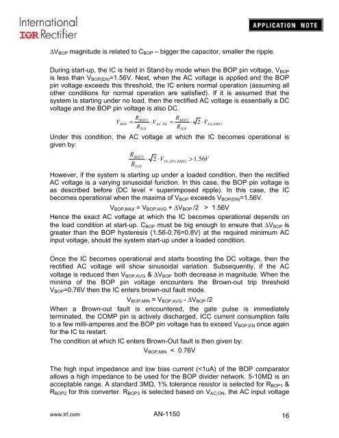
system is starting under no load, then the rectified AC voltage is essentially a DC<br />
voltage and the BOP pin voltage is also DC.<br />
V<br />
BOP<br />
R<br />
=<br />
R<br />
BOP3<br />
TOT<br />
⋅V<br />
AC , PK<br />
R<br />
=<br />
R<br />
BOP3<br />
TOT<br />
⋅<br />
2 ⋅VIN<br />
( RMS )<br />
Under this condition, the AC voltage at which the IC becomes operational is<br />
given by:<br />
R<br />
R<br />
BOP3<br />
TOT<br />
⋅<br />
2 ⋅VIN<br />
, ON ( RMS )<br />
> 1.56V<br />
However, if the system is starting up under a loaded condition, then the rectified<br />
AC voltage is a varying sinusoidal function. In this case, the BOP pin voltage is<br />
as described before (DC level + superimposed ripple). In this case, the IC<br />
becomes operational when the maxima of V BOP exceeds V BOP(EN) =1.56V.<br />
V BOP,MAX = V BOP,AVG + ∆V BOP /2 > 1.56V<br />
Hence the exact AC voltage at which the IC becomes operational depends on<br />
the load condition at start-up. C BOP must be big enough to ensure that ∆V BOP is<br />
greater than the BOP hysteresis (1.56-0.76=0.8V) at the required minimum AC<br />
input voltage, should the system start-up under a loaded condition.<br />
Once the IC becomes operational and starts boosting the DC voltage, then the<br />
rectified AC voltage will show sinusoidal variation. Subsequently, if the AC<br />
voltage is reduced then V BOP,AVG & ∆V BOP both decrease in magnitude. When the<br />
minima of the BOP pin voltage encounters the Brown-out trip threshold<br />
V BOP =0.76V then the IC enters brown-out fault mode.<br />
V BOP,MIN = V BOP,AVG - ∆V BOP /2<br />
When a Brown-out fault is encountered, the gate pulse is immediately<br />
terminated, the COMP pin is actively discharged, ICC current consumption falls<br />
to a few milli-amperes and the BOP pin voltage has to exceed V BOP,EN once again<br />
for the IC to restart.<br />
The condition at which IC enters Brown-Out fault is then given by:<br />
V BOP,MIN < 0.76V<br />
The high input impedance and low bias current (


