Doppler Weather Radar - METNET - India Meteorological Department
Doppler Weather Radar - METNET - India Meteorological Department
Doppler Weather Radar - METNET - India Meteorological Department

You also want an ePaper? Increase the reach of your titles
YUMPU automatically turns print PDFs into web optimized ePapers that Google loves.
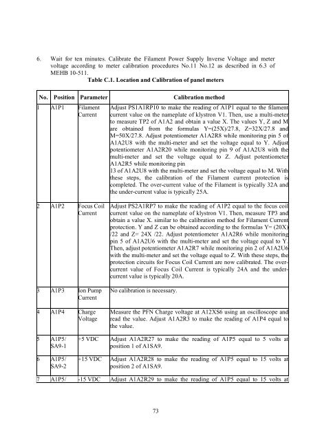
6. Wait for ten minutes. Calibrate the Filament Power Supply Inverse Voltage and meter<br />
voltage according to meter calibration procedures No.11 No.12 as described in 6.3 of<br />
MEHB 10-511.<br />
Table C.1. Location and Calibration of panel meters<br />
No. Position Parameter<br />
1 A1P1 Filament<br />
Current<br />
Calibration method<br />
Adjust PS1A1RP10 to make the reading of A1P1 equal to the filament<br />
current value on the nameplate of klystron V1. Then, use a multi-meter<br />
to measure TP2 of A1A2 and obtain a value X. The values Y, Z and M<br />
are obtained from the formulas Y=(25X)/27.8, Z=32X/27.8 and<br />
M=50X/27.8. Adjust potentiometer A1A2R8 while monitoring pin 5 of<br />
A1A2U8 with the multi-meter and set the voltage equal to Y. Adjust<br />
potentiometer A1A2R20 while monitoring pin 9 of A1A2U8 with the<br />
multi-meter and set the voltage equal to Z. Adjust potentiometer<br />
A1A2R5 while monitoring pin<br />
13 of A1A2U8 with the multi-meter and set the voltage equal to M. With<br />
these steps, the calibration of the Filament current protection is<br />
completed. The over-current value of the Filament is typically 32A and<br />
the under-current value is typically 25A.<br />
2 A1P2 Focus Coil<br />
Current<br />
3 A1P3 Ion Pump<br />
Current<br />
4 A1P4 Charge<br />
Voltage<br />
Adjust PS2A1RP7 to make the reading of A1P2 equal to the focus coil<br />
current value on the nameplate of klystron V1. Then, measure TP3 and<br />
obtain a value X. similar to the calibration method for Filament Current<br />
protection. Y and Z can be obtained according to the formulas Y= (20X)<br />
/22 and Z= 24X /22. Adjust potentiometer A1A2R6 while monitoring<br />
pin 5 of A1A2U6 with the multi-meter and set the voltage equal to Y.<br />
Then, adjust potentiometer A1A2R7 while monitoring pin 2 of A1A2U6<br />
with the multi-meter and set the voltage equal to Z. With these steps, the<br />
protection circuits for Focus Coil Current are now calibrated. The overcurrent<br />
value of Focus Coil Current is typically 24A and the undercurrent<br />
value is typically 20A.<br />
No calibration is necessary.<br />
Measure the PFN Charge voltage at A12XS6 using an oscilloscope and<br />
read the value. Adjust A1A2R3 to make the reading of A1P4 equal to<br />
the value.<br />
5 A1P5/<br />
SA9-1<br />
6 A1P5/<br />
SA9-2<br />
+5 VDC Adjust A1A2R27 to make the reading of A1P5 equal to 5 volts at<br />
position 1 of A1SA9.<br />
+15 VDC Adjust A1A2R28 to make the reading of A1P5 equal to 15 volts at<br />
position 2 of A1SA9.<br />
7 A1P5/ -15 VDC Adjust A1A2R29 to make the reading of A1P5 equal to 15 volts at<br />
73