

MAX9272 28-Bit GMSL Deserializer for Coax or STP Cable
MAX9272 28-Bit GMSL Deserializer for Coax or STP Cable
MAX9272 28-Bit GMSL Deserializer for Coax or STP Cable

You also want an ePaper? Increase the reach of your titles
YUMPU automatically turns print PDFs into web optimized ePapers that Google loves.
<strong>MAX9272</strong><br />
<strong>28</strong>-<strong>Bit</strong> <strong>GMSL</strong> <strong>Deserializer</strong> <strong>f<strong>or</strong></strong> <strong>Coax</strong> <strong>or</strong> <strong>STP</strong> <strong>Cable</strong><br />
IN+ - IN-<br />
IN+/-<br />
t LOCK<br />
PWDN<br />
V IH1<br />
LOCK<br />
V OH<br />
LOCK<br />
t PU<br />
V OH<br />
PWDN MUST BE HIGH<br />
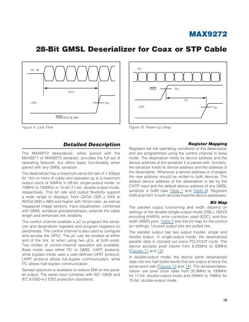
Figure 9. Lock Time<br />
Figure 10. Power-Up Delay<br />
Detailed Description<br />
The <strong>MAX9272</strong> deserializer, when paired with the<br />
MAX9271 <strong>or</strong> MAX9273 serializer, provides the full set of<br />
operating features, but offers basic functionality when<br />
paired with any <strong>GMSL</strong> serializer.<br />
The deserializer has a maximum serial-bit rate of 1.5Gbps<br />
<strong>f<strong>or</strong></strong> 15m <strong>or</strong> m<strong>or</strong>e of cable and operates up to a maximum<br />
output clock of 50MHz in <strong>28</strong>-bit, single-output mode, <strong>or</strong><br />
75MHz to 100MHz in 15-bit /11-bit, double-output mode,<br />
respectively. This bit rate and output flexibility supp<strong>or</strong>t<br />
a wide range of displays, from QVGA (320 x 240) to<br />
WVGA (800 x 480) and higher with 18-bit col<strong>or</strong>, as well as<br />
megapixel image sens<strong>or</strong>s. Input equalization, combined<br />
with <strong>GMSL</strong> serializer pre/deemphasis, extends the cable<br />
length and enhances link reliability<br />
The control channel enables a FC to program the serializer<br />
and deserializer registers and program registers on<br />
peripherals. The control channel is also used to configure<br />
and access the GPIO. The FC can be located at either<br />
end of the link, <strong>or</strong> when using two FCs, at both ends.<br />
Two modes of control-channel operation are available.<br />
Base mode uses either I 2 C <strong>or</strong> <strong>GMSL</strong> UART protocol,<br />
while bypass mode uses a user-defined UART protocol.<br />
UART protocol allows full-duplex communication, while<br />
I 2 C allows half-duplex communication.<br />
Spread spectrum is available to reduce EMI on the parallel<br />
output. The serial input complies with ISO 10605 and<br />
IEC 61000-4-2 ESD protection standards.<br />
Register Mapping<br />
Registers set the operating conditions of the deserializer<br />
and are programmed using the control channel in base<br />
mode. The deserializer holds its device address and the<br />
device address of the serializer it is paired with. Similarly,<br />
the serializer holds its device address and the address of<br />
the deserializer. Whenever a device address is changed,<br />
the new address should be written to both devices. The<br />
default device address of the deserializer is set by the<br />
CX/TP input and the default device address of any <strong>GMSL</strong><br />
serializer is 0x80 (see Table 1 and Table 8). Registers<br />
0x00 and 0x01 in both devices hold the device addresses.<br />
<strong>Bit</strong> Map<br />
The parallel output functioning and width depend on<br />
settings of the double-/single-output mode (DBL), HS/VS<br />
encoding (HVEN), err<strong>or</strong> c<strong>or</strong>rection used (EDC), and bus<br />
width (BWS) pins. Table 2 lists the bit map <strong>f<strong>or</strong></strong> the control<br />
pin settings. Unused output bits are pulled low.<br />
The parallel output has two output modes: single and<br />
double output. In single-output mode, the deserialized<br />
parallel data is clocked out every PCLKOUT cycle. The<br />
device accepts pixel clocks from 6.25MHz to 50MHz<br />
(Figures 11 and 12).<br />
In double-output mode, the device splits deserialized<br />
data into two half-sized w<strong>or</strong>ds that are output at twice the<br />
serial-w<strong>or</strong>d rate (Figures 13 and 14). The serializer/deserializer<br />
use pixel clock rates from 33.3MHz to 100MHz<br />
<strong>f<strong>or</strong></strong> 11-bit, double-output mode and 25MHz to 75MHz <strong>f<strong>or</strong></strong><br />
15-bit, double-output mode.<br />
18

![P-CAD EDA - [Sheet1]](https://img.yumpu.com/49470492/1/190x115/p-cad-eda-sheet1.jpg?quality=85)


