

MAX9272 28-Bit GMSL Deserializer for Coax or STP Cable
MAX9272 28-Bit GMSL Deserializer for Coax or STP Cable
MAX9272 28-Bit GMSL Deserializer for Coax or STP Cable

You also want an ePaper? Increase the reach of your titles
YUMPU automatically turns print PDFs into web optimized ePapers that Google loves.
<strong>MAX9272</strong><br />
<strong>28</strong>-<strong>Bit</strong> <strong>GMSL</strong> <strong>Deserializer</strong> <strong>f<strong>or</strong></strong> <strong>Coax</strong> <strong>or</strong> <strong>STP</strong> <strong>Cable</strong><br />
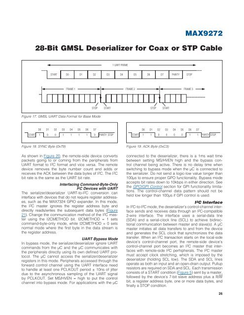
1 UART FRAME<br />
START D0 D1 D2 D3 D4 D5 D6 D7 PARITY STOP<br />
FRAME 1 FRAME 2 FRAME 3<br />
STOP START STOP START<br />
Figure 17. <strong>GMSL</strong> UART Data F<strong>or</strong>mat <strong>f<strong>or</strong></strong> Base Mode<br />
D0<br />
D1 D2 D3 D4 D5 D6 D7<br />
D0<br />
D1 D2 D3 D4 D5 D6 D7<br />
START<br />
1 0 0 1 1 1 1 0<br />
PARITY STOP<br />
START<br />
1 1 0 0 0 0 1 1<br />
PARITY STOP<br />
Figure 18. SYNC Byte (0x79)<br />
As shown in Figure 20, the remote-side device converts<br />
packets going to <strong>or</strong> coming from the peripherals from<br />
UART <strong>f<strong>or</strong></strong>mat to I 2 C <strong>f<strong>or</strong></strong>mat and vice versa. The remote<br />
device removes the byte number count and adds <strong>or</strong><br />
receives the ACK between the data bytes of I 2 C. The I 2 C<br />
bit rate is the same as the UART bit rate.<br />
Interfacing Command-Byte-Only<br />
I 2 C Devices with UART<br />
The serializer/deserializer UART-to-I 2 C conversion can<br />
interface with devices that do not require register addresses,<br />
such as the MAX7324 GPIO expander. In this mode,<br />
the I 2 C master ign<strong>or</strong>es the register address byte and<br />
directly reads/writes the subsequent data bytes (Figure<br />
21). Change the communication method of the I 2 C master<br />
using the I2CMETHOD bit. I2CMETHOD = 1 sets<br />
command-byte-only mode, while I2CMETHOD = 0 sets<br />
n<strong>or</strong>mal mode where the first byte in the data stream is<br />
the register address.<br />
UART Bypass Mode<br />
In bypass mode, the serializer/deserializer ign<strong>or</strong>e UART<br />
commands from the FC and the FC communicates with<br />
the peripherals directly using its own defined UART protocol.<br />
The FC cannot access the serializer/deserializer<br />
registers in this mode. Peripherals accessed through the<br />
<strong>f<strong>or</strong></strong>ward control channel using the UART interface need<br />
to handle at least one PCLKOUT period Q 10ns of jitter<br />
due to the asynchronous sampling of the UART signal<br />
by PCLKOUT. Set MS/HVEN = high to put the control<br />
channel into bypass mode. F<strong>or</strong> applications with the FC<br />
Figure 19. ACK Byte (0xC3)<br />
connected to the deserializer, there is a 1ms wait time<br />
between setting MS/HVEN high and the bypass control<br />
channel being active. There is no delay time when<br />
switching to bypass mode when the FC is connected to<br />
the serializer. Do not send a logic-low value longer than<br />
100Fs to ensure proper GPO functionality. Bypass mode<br />
accepts bit rates down to 10kbps in either direction. See<br />
the GPO/GPI Control section <strong>f<strong>or</strong></strong> GPI functionality limitations.<br />
The control-channel data pattern should not be<br />
held low longer than 100Fs if GPI control is used.<br />
I 2 C Interface<br />
In I 2 C-to-I 2 C mode, the deserializer’s control-channel interface<br />
sends and receives data through an I 2 C-compatible<br />
2-wire interface. The interface uses a serial-data line<br />
(SDA) and a serial-clock line (SCL) to achieve bidirectional<br />
communication between master and slave(s). A FC<br />
master initiates all data transfers to and from the device<br />
and generates the SCL clock that synchronizes the data<br />
transfer. When an I 2 C transaction starts on the local-side<br />
device’s control-channel p<strong>or</strong>t, the remote-side device’s<br />
control-channel p<strong>or</strong>t becomes an I 2 C master that interfaces<br />
with remote-side I 2 C perhipherals. The I 2 C master<br />
must accept clock stretching, which is imposed by the<br />
deserializer (holding SCL low). The SDA and SCL lines<br />
operate as both an input and an open-drain output. Pullup<br />
resist<strong>or</strong>s are required on SDA and SCL. Each transmission<br />
consists of a START condition (Figure 5) sent by a master,<br />
followed by the device’s 7-bit slave address plus a R/W<br />
bit, a register address byte, one <strong>or</strong> m<strong>or</strong>e data bytes, and<br />
finally a STOP condition.<br />
26

![P-CAD EDA - [Sheet1]](https://img.yumpu.com/49470492/1/190x115/p-cad-eda-sheet1.jpg?quality=85)


