

MAX9272 28-Bit GMSL Deserializer for Coax or STP Cable
MAX9272 28-Bit GMSL Deserializer for Coax or STP Cable
MAX9272 28-Bit GMSL Deserializer for Coax or STP Cable

You also want an ePaper? Increase the reach of your titles
YUMPU automatically turns print PDFs into web optimized ePapers that Google loves.
<strong>MAX9272</strong><br />
<strong>28</strong>-<strong>Bit</strong> <strong>GMSL</strong> <strong>Deserializer</strong> <strong>f<strong>or</strong></strong> <strong>Coax</strong> <strong>or</strong> <strong>STP</strong> <strong>Cable</strong><br />
Serial Link Signaling and Data F<strong>or</strong>mat<br />
The serializer uses differential CML signaling to drive<br />
twisted-pair cable and single-ended CML to drive<br />
coax cable with programmable pre/deemphasis and<br />
AC-coupling. The deserializer uses AC-coupling and<br />
programmable channel equalization.<br />
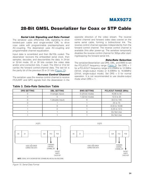
Input data is scrambled and then 8b/10b coded. The<br />
deserializer recovers the embedded serial clock, then<br />
samples, decodes, and descrambles the data. In 24-bit<br />
<strong>or</strong> 32-bit mode, 22 <strong>or</strong> 30 bits contain the video data<br />
and/<strong>or</strong> err<strong>or</strong>-c<strong>or</strong>rection bits, if used. The 23rd <strong>or</strong> 31st bit<br />
carries the <strong>f<strong>or</strong></strong>ward control-channel data. The last bit is<br />
the parity bit of the previous 23 <strong>or</strong> 31 bits (Figure 15).<br />
Reverse Control Channel<br />
The serializer uses the reverse control channel to receive<br />
I 2 C/UART and GPO signals from the deserializer in the<br />
opposite direction of the video stream. The reverse<br />
control channel and <strong>f<strong>or</strong></strong>ward video data coexist on the<br />
same serial cable, <strong>f<strong>or</strong></strong>ming a bidirectional link. The<br />
reverse control channel operates independently from the<br />
<strong>f<strong>or</strong></strong>ward control channel. The reverse control channel is<br />
available 2ms after power-up. The serializer temp<strong>or</strong>arily<br />
disables the reverse control channel <strong>f<strong>or</strong></strong> 350Fs after starting/stopping<br />
the <strong>f<strong>or</strong></strong>ward serial link.<br />
Data-Rate Selection<br />
The serializer/deserializer use DRS, DBL, and BWS to set<br />
the PCLKOUT frequency range (Table 3). Set DRS = 1<br />
<strong>f<strong>or</strong></strong> a PCLKOUT frequency range of 6.25MHz to 12.5MHz<br />
(32-bit, single-output mode) <strong>or</strong> 8.33MHz to 16.66MHz<br />
(24-bit, single-output mode). Set DRS = 0 <strong>f<strong>or</strong></strong> n<strong>or</strong>mal<br />
operation. It is not recommended to use double-output<br />
mode when DRS = 1.<br />
Table 3. Data-Rate Selection Table<br />
DRS SETTING DBL SETTING BWS SETTING PCLKOUT RANGE (MHz)<br />
0 0 (single input) 0 (24-bit mode) 16.66 to 50<br />
0 0 1 (32-bit mode) 12.5 to 35<br />
0 1 (double input) 0 33.3 to 100<br />
0 1 1 25 to 75<br />
1 0 0 8.33 to 16.66<br />
1 0 1 6.25 to 12.5<br />
1 1 0 Do Not Use<br />
1 1 1 Do Not Use<br />
24 BITS 32 BITS<br />
D0 D1 D21 FCC PCB D0 D1 D29 FCC PCB<br />
VIDEO AND ERROR<br />
CORRECTION DATA<br />
FORWARD<br />
CONTROL-<br />
CHANNEL BIT<br />
PACKET<br />
PARITY<br />
CHECK BIT<br />
NOTE: SERIAL DATA SHOWN BEFORE SCRAMBLING AND 8b/10b ENCODING<br />
VIDEO AND ERROR<br />
CORRECTION DATA<br />
FORWARD<br />
CONTROL-<br />
CHANNEL BIT<br />
PACKET<br />
PARITY<br />
CHECK BIT<br />
Figure 15. Serial-Data F<strong>or</strong>mat<br />
24

![P-CAD EDA - [Sheet1]](https://img.yumpu.com/49470492/1/190x115/p-cad-eda-sheet1.jpg?quality=85)


