EWP Hangers - USP Connectors
EWP Hangers - USP Connectors
EWP Hangers - USP Connectors

You also want an ePaper? Increase the reach of your titles
YUMPU automatically turns print PDFs into web optimized ePapers that Google loves.
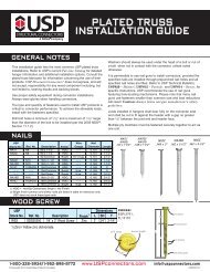
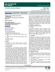
Wood Screw Applications – WS series<br />
Joining 2, 3, or 4 Ply Wood Trusses<br />
© Copyright 2013 <strong>USP</strong> Structural <strong>Connectors</strong>®<br />
The installation instructions and design example shown below are intended for a design professional who will be<br />
responsible for determining the location and number of wood screws to adequately transfer all loads on the truss.<br />
Installation:<br />
• Screw spacing shall not be greater than 24˝ on centre and less than 4˝ on centre. However, the location of any<br />
individual screw may be adjusted up to one-half the required screw spacing to avoid lumber defects or interference<br />
with other hardware.<br />
• Load or hanger spacing shall not be greater than 24˝ centre-to-centre.<br />
• The last truss ply must have a minimum of 11/4˝ of screw penetration and no more than 1/8˝ gap between each ply.<br />
• Screws cannot be installed through metal truss plates unless the Truss Engineer approves predrilling.<br />
• On 2x4 members, use one row of wood screws. On 2x6 and 2x8 use two rows, and on 2x10 use three rows. Stagger<br />
all rows.<br />
• The truss bottom chord shall have lateral bracing installed as called out by the Truss Engineer to prevent any<br />
displacement from torsional forces.<br />
• Install screws from one side<br />
without flipping the truss.<br />
• Top and bottom chords<br />
require screws and in some<br />
cases the webs may require<br />
screws.<br />
• All lateral bracing should be<br />
attached to each truss ply.<br />
• Increase edge and end<br />
distances if wood splitting<br />
occurs.<br />
2 1 /2˝ Min.<br />
1 1 /2˝ Min.<br />
Start screws on<br />
face that carries<br />
hanger on load<br />
Spacing<br />
4˝ min. – 24˝ max.<br />
1˝ min. Recommended (Typ)<br />
Spacing<br />
4˝ min. – 24˝ max.<br />
4˝ min<br />
1 1 /2˝ Min.<br />
End of<br />
chord<br />
Fasteners<br />
Description<br />
Length (in)<br />
Factored Shear Loads (100%.) 1,2,3<br />
Shear<br />
S-P-F<br />
<strong>USP</strong><br />
Plane<br />
DF-L<br />
Stock No. Ref. No. in mm L SH T Finish Location Lbs kN Lbs kN<br />
WS3 SDS25300 3 3/4 2 Zinc SH, T 387 1.72 332 1.48<br />
WS45 SDS25412 3 Zinc SH, T 543 2.42 480 2.14<br />
WS6 SDS25600 6 4 Zinc SH, T 543 2.42 480 2.14<br />
<br />
2) The Truss Engineer shall apply all applicable adjustment factors.<br />
<br />
<br />
New products or updated product information are designated in red font.<br />
3 Ply with Mixed Wood Species:<br />
Bottom Chord: 2x6 Douglas Fir-Larch<br />
Top Chord: 2x4 Spruce-Pine-Fir<br />
WS45 Wood Screw Factored Resistance:<br />
(Assume shear plane across the screw shank)<br />
Douglas Fir-Larch: 543 Ibs. each at 100%<br />
Spruce-Pine-Fir: 480 lbs. each at 100%<br />
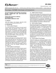
Design Example<br />
Truss top chord<br />
Required Loads:<br />
Bottom Chord Load: 500 plf<br />
Top Chord Load: 60 plf<br />
Bottom Chord Wood Screw Spacing:<br />
Using 2 rows of WS45 Wood Screws in 2x6<br />
2 x 543/500 x<br />
# Plies<br />
= 3.26 ft.<br />
# Plies - 1<br />
Use maximum spacing of 24˝.<br />
Top Chord Wood Screw Spacing:<br />
Only 1 row of WS45 Wood Screws in 2x4 member<br />
1 x 480/60 x<br />
# Plies<br />
= 12.0 ft.<br />
# Plies - 1<br />
Use maximum spacing of 24˝.<br />
Truss bottom chord<br />
Truss span<br />
Typical Truss Profile (profile may vary)<br />
continued on next page<br />
1-800-328-5934 • www.<strong>USP</strong>connectors.com 17<br />
<strong>USP</strong>2240-131