STARTING GUIDE FRENIC-Eco . FRN-F1 - Welcome to Fuji Electric
STARTING GUIDE FRENIC-Eco . FRN-F1 - Welcome to Fuji Electric
STARTING GUIDE FRENIC-Eco . FRN-F1 - Welcome to Fuji Electric

You also want an ePaper? Increase the reach of your titles
YUMPU automatically turns print PDFs into web optimized ePapers that Google loves.
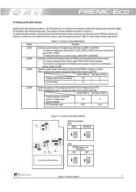
3.6 Setting up the slide switches<br />
Switching the slide switches located on the PCB allows you <strong>to</strong> cus<strong>to</strong>mize the operation mode of the analog output terminals, digital<br />
I/O terminals, and communication ports. The locations of those switches are shown in Figure 3.1.<br />
To switch the slide switches, remove the front and terminal block covers, so that you can see the control PCB that contains the<br />
switches. Furthermore, for models of 37 kW or above, open the keypad enclosure. Table 3.1 lists function of each slide switch.<br />
Table 3.1. Function of Each Slide Switch<br />
Switch Function<br />
SW1 Switches service mode of the digital input terminals for SINK or SOURCE.<br />
- To make the digital input terminal [X1] <strong>to</strong> [X5], [FWD] or [REV] serve as a current sink,<br />
switch SW1 <strong>to</strong> SINK.<br />
- To make them serve as a current source, switch SW1 <strong>to</strong> SOURCE.<br />
SW3 Switches on/off the terminating resis<strong>to</strong>r of RS485 communications port of the inverter.<br />
- To connect a keypad <strong>to</strong> the inverter switch SW3 <strong>to</strong> OFF (fac<strong>to</strong>ry default).<br />
- If the inverter is connected <strong>to</strong> the RS485 communications network as a termination<br />
device, switch it <strong>to</strong> ON.<br />
SW4 Switches output mode of the analog output terminal FMA <strong>to</strong> voltage or current.<br />
When switching this switch, change also data of the function code F29.<br />
Switch SW4 <strong>to</strong>: Set data of F29 <strong>to</strong>:<br />
Voltage output (Fac<strong>to</strong>ry default) VO 0<br />
Current output IO 1<br />
SW5 Switches property of the analog input terminal V2 for voltage input or PTC.<br />
When switching this switch, change also data of the function code H26<br />
Switch SW5 <strong>to</strong>: Set data of H26 <strong>to</strong>:<br />
Analog frequency command<br />
source in voltage input<br />
(Fac<strong>to</strong>ry default)<br />
V2 0<br />
PTC thermis<strong>to</strong>r input PTC 1 or 2<br />
Figure 3.1. Location of the slide switches<br />
Switching example<br />
SW1<br />
SINK SOURCE<br />
SW3<br />
Chapter 3: <strong>Electric</strong>al installation<br />
RS485 comm. port<br />
termina<strong>to</strong>r<br />
ON OFF<br />
9