STARTING GUIDE FRENIC-Eco . FRN-F1 - Welcome to Fuji Electric
STARTING GUIDE FRENIC-Eco . FRN-F1 - Welcome to Fuji Electric
STARTING GUIDE FRENIC-Eco . FRN-F1 - Welcome to Fuji Electric

Create successful ePaper yourself
Turn your PDF publications into a flip-book with our unique Google optimized e-Paper software.
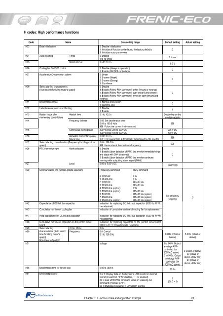
H codes: High performance functions<br />
Code Name Data setting range Default setting Actual setting<br />
H03 Data initialization 0: Disable initialization<br />
1: Initialize all function code data <strong>to</strong> the fac<strong>to</strong>ry defaults<br />
2: Initialize mo<strong>to</strong>r parameters<br />
H04 Au<strong>to</strong>-resetting<br />
Times 0: Disable<br />
1 <strong>to</strong> 10 times<br />
H05<br />
Reset interval 0.5 <strong>to</strong> 20.0 s<br />
H06 Cooling fan ON/OFF control 0: Disable (Always in operation)<br />
1: Enable (ON/OFF controllable)<br />
0<br />
H07 Acceleration/Deceleration pattern 0: Linear<br />
1: S-curve (Weak)<br />
2: S-curve (Strong)<br />
3: Curvilinear<br />
0<br />
H09 Select starting characteristics<br />
0: Disable<br />
(Au<strong>to</strong> search for idling mo<strong>to</strong>r's speed)<br />
3: Enable (Follow RUN command, either forward or reverse)<br />
4: Enable (Follow RUN command, both forward and reverse)<br />
5: Enable (Follow RUN command, inversely both forward and<br />
reverse)<br />
0<br />
H11 Deceleration mode 0: Normal deceleration<br />
1: Coast-<strong>to</strong>-s<strong>to</strong>p<br />
0<br />
H12 Instantaneous overcurrent limiting 0: Disable<br />
1: Enable<br />
1<br />
H13 Restart mode after<br />
Restart time 0.1 <strong>to</strong> 10.0 s Depending on the<br />
momentary power failure<br />
inverter capacity<br />
H14 Frequency fall rate 0.00: Set deceleration time<br />
0.01 <strong>to</strong> 100.0 Hz/s<br />
999: Follow the current limit command<br />
999<br />
H15 Continuous running level 200V series: 200 <strong>to</strong> 300VDC<br />
235 V DC<br />
400V series: 400 <strong>to</strong> 600VDC<br />
470 V DC<br />
H16<br />
Allowable momentary power<br />
failure time<br />
0.0 <strong>to</strong> 30.0 s<br />
999: The longest time au<strong>to</strong>matically determined by the inverter<br />
999<br />
H17 Select starting characteristics (Frequency for idling mo<strong>to</strong>r's<br />
speed)<br />
0.0 <strong>to</strong> 120.0 Hz<br />
999: Harmonize at the maximum frequency<br />
999<br />
H26 PTC thermis<strong>to</strong>r input Mode selection 0: Disable<br />
1: Enable (Upon detection of PTC, the inverter immediately trips<br />
and s<strong>to</strong>ps with OH4 displayed)<br />
2: Enable (Upon detection of PTC, the inverter continues<br />
running while outputting alarm signal (THM))<br />
0<br />
H27<br />
Level 0.00 <strong>to</strong> 5.00 V DC<br />
1.60 V DC<br />
H30 Communication link function (Mode selection) Frequency command<br />
0: F01/C30<br />
1: RS485 link<br />
2: F01/C30<br />
3: RS485 link<br />
4: RS485 link (option)<br />
5: RS485 link (option)<br />
6: F01/C30<br />
7: RS485 link<br />
8: RS485 link (option)<br />
RUN command<br />
F02<br />
F02<br />
RS485 link<br />
RS485 link<br />
F02<br />
RS485 link<br />
RS485 link (option)<br />
RS485 link (option)<br />
RS485 link (option)<br />
H42 Capacitance of DC link bus capaci<strong>to</strong>r Indication for replacing DC link bus capaci<strong>to</strong>r (0000 <strong>to</strong> FFFF:<br />
Hexadecimal)<br />
H43 Cumulative run time of cooling fan Indication of cumulative run time of cooling fan for replacement<br />
Chapter 6: Function codes and application example 20<br />
0<br />
0 times<br />
5.0 s<br />
Set at fac<strong>to</strong>ry<br />
shipping<br />
H47 Initial capacitance of DC link bus capaci<strong>to</strong>r Indication for replacing DC link bus capaci<strong>to</strong>r (0000 <strong>to</strong> FFFF:<br />
Hexadecimal)<br />
H48 Cumulative run time of capaci<strong>to</strong>rs on the printed circuit Indication for replacing capaci<strong>to</strong>rs on the printed circuit board<br />
board<br />
(0000 <strong>to</strong> FFFF: Hexadecimal). Resetable<br />
H49 Select starting<br />
0.0 <strong>to</strong> 10.0 s 0.0 s<br />
H50 characteristics (Au<strong>to</strong> search Frequency 0.0: Cancel<br />
time for idling mo<strong>to</strong>r's<br />
0.1 <strong>to</strong> 120.0 Hz<br />
0.0 Hz (22kW or<br />
speed)<br />
Non-linear V/f pattern<br />
below)<br />
H51 Voltage 0 <strong>to</strong> 240V: Output<br />
a voltage AVRcontrolled<br />
(for<br />
200V AC series)<br />
0 <strong>to</strong> 500V: Output<br />
a voltage AVRcontrolled<br />
(for<br />
400V AC series)<br />
H56 Deceleration time for forced s<strong>to</strong>p 0.00 <strong>to</strong> 3600 s<br />
20.0 s<br />
H61 UP/DOWN Control 1 or 3: Display data on the keypad´s LED moni<strong>to</strong>r in decimal<br />
format (in each bit, “0” for disabled, “1” for enabled)<br />
Bit 0: Last UP/DOWN command value on releasing run<br />
command (Prefixed <strong>to</strong> “1”)<br />
Bit 1: Multistep Frequency + UP/DOWN Control<br />
1<br />
(Bit 0 = 1)<br />
0<br />
5.0 Hz (30kW or<br />
above)<br />
0 (22kW or below)<br />
20 (30kW or<br />
above, 200V ser.)<br />
40 (30kW or<br />
above, 400V ser.)