STARTING GUIDE FRENIC-Eco . FRN-F1 - Welcome to Fuji Electric
STARTING GUIDE FRENIC-Eco . FRN-F1 - Welcome to Fuji Electric
STARTING GUIDE FRENIC-Eco . FRN-F1 - Welcome to Fuji Electric

You also want an ePaper? Increase the reach of your titles
YUMPU automatically turns print PDFs into web optimized ePapers that Google loves.
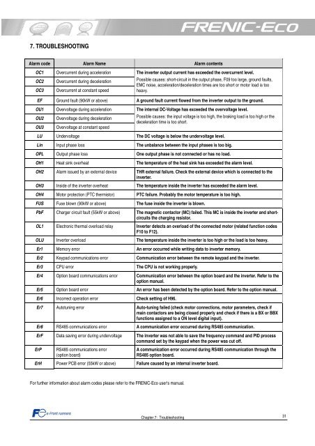
7. TROUBLESHOOTING<br />
Alarm code Alarm Name Alarm contents<br />
OC1 Overcurrent during acceleration<br />
OC2 Overcurrent during deceleration<br />
OC3 Overcurrent at constant speed<br />
The inverter output current has exceeded the overcurrent level.<br />
Possible causes: short-circuit in the output phase, F09 <strong>to</strong>o large, ground faults,<br />
EMC noise, acceleration/deceleration times are <strong>to</strong>o short or mo<strong>to</strong>r load is <strong>to</strong>o<br />
heavy.<br />
EF Ground fault (90kW or above) A ground fault current flowed from the inverter output <strong>to</strong> the ground.<br />
OU1 Overvoltage during acceleration<br />
OU2 Overvoltage during deceleration<br />
OU3 Overvoltage at constant speed<br />
The internal DC-Voltage has exceeded the overvoltage level.<br />
Possible causes: the input voltage is <strong>to</strong>o high, the braking load is <strong>to</strong>o high or the<br />
deceleration time is <strong>to</strong>o short.<br />
LU Undervoltage The DC voltage is below the undervoltage level.<br />
Lin Input phase loss The unbalance between the input phases is <strong>to</strong>o big.<br />
OPL Output phase loss One output phase is not connected or has no load.<br />
OH1 Heat sink overheat The temperature of the heat sink has exceeded the alarm level.<br />
OH2 Alarm issued by an external device THR external failure. Check the external device which is connected <strong>to</strong> the<br />
inverter.<br />
OH3 Inside of the inverter overheat The temperature inside the inverter has exceeded the alarm level.<br />
OH4 Mo<strong>to</strong>r protection (PTC thermis<strong>to</strong>r) PTC failure. Probably the mo<strong>to</strong>r temperature is <strong>to</strong>o high.<br />
FUS Fuse blown (90kW or above) The fuse inside the inverter is blown.<br />
PbF Charger circuit fault (55kW or above) The magnetic contac<strong>to</strong>r (MC) failed. This MC is inside the inverter and shortcircuits<br />
the charging resis<strong>to</strong>r.<br />
OL1 Electronic thermal overload relay Inverter detects an overload of the connected mo<strong>to</strong>r (related function codes<br />
<strong>F1</strong>0 <strong>to</strong> <strong>F1</strong>2).<br />
OLU Inverter overload The temperature inside the inverter is <strong>to</strong>o high or the load is <strong>to</strong>o heavy.<br />
Er1 Memory error An error occurred while writing data <strong>to</strong> inverter memory.<br />
Er2 Keypad communications error Communication error between the remote keypad and the inverter.<br />
Er3 CPU error The CPU is not working properly.<br />
Er4 Option board communications error Communication error between the option board and the inverter. Refer <strong>to</strong> the<br />
option manual.<br />
Er5 Option board error An error has been detected by the option board. Refer <strong>to</strong> the option manual.<br />
Er6 Incorrect operation error Check setting of H96.<br />
Er7 Au<strong>to</strong>tuning error Au<strong>to</strong>-tuning failed (check mo<strong>to</strong>r connections, mo<strong>to</strong>r parameters, check if<br />
main contac<strong>to</strong>rs are being closed properly and check if there is a BX or BBX<br />
functions assigned <strong>to</strong> a ON level digital input).<br />
Er8 RS485 communications error A communication error occurred during RS485 communication.<br />
ErF Data saving error during undervoltage The inverter was not able <strong>to</strong> save the frequency command and PID process<br />
command set by the keypad when the power was cut off.<br />
ErP RS485 communications error<br />
(option board)<br />
A communication error occurred during RS485 communication through the<br />
RS485 option board.<br />
ErH Power PCB error (55kW or above) Failure caused by an internal inverter board.<br />
For further information about alarm codes please refer <strong>to</strong> the <strong>FRENIC</strong>-<strong>Eco</strong> user's manual.<br />
Chapter 7: Troubleshooting<br />
31