STARTING GUIDE FRENIC-Eco . FRN-F1 - Welcome to Fuji Electric
STARTING GUIDE FRENIC-Eco . FRN-F1 - Welcome to Fuji Electric
STARTING GUIDE FRENIC-Eco . FRN-F1 - Welcome to Fuji Electric

You also want an ePaper? Increase the reach of your titles
YUMPU automatically turns print PDFs into web optimized ePapers that Google loves.
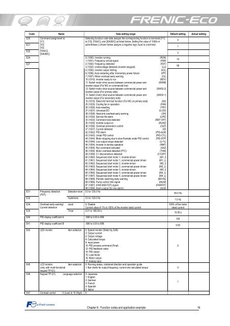
E20<br />
E21<br />
E22<br />
E24<br />
E27<br />
E31<br />
E32<br />
Code Name Data setting range Default setting Actual setting<br />
Command assignment <strong>to</strong>:<br />
[Y1]<br />
[Y2]<br />
[Y3]<br />
[Y5A/C]<br />
[30A/B/C]<br />
Frequency detection<br />
(FDT)<br />
Selecting function code data assigns the corresponding function <strong>to</strong> terminals [Y1]<br />
<strong>to</strong> [Y3], [Y5A/C], and [30A/B/C] as listed below. Setting the value of 1000s in<br />
parentheses () shown below assigns a negative logic input <strong>to</strong> a terminal.<br />
0 (1000): Inverter running<br />
1 (1001): Frequency arrival signal<br />
2 (1002): Frequency detected<br />
3 (1003): Undervoltage detected (inverter s<strong>to</strong>pped)<br />
5 (1005): Inverter output limiting<br />
6 (1006): Au<strong>to</strong>-restarting after momentary power failure<br />
7 (1007): Mo<strong>to</strong>r overload early warning<br />
10 (1010): Inverter ready <strong>to</strong> run<br />
11: Switch mo<strong>to</strong>r drive source between commercial power and<br />
inverter output (For MC on commercial line)<br />
12: Switch mo<strong>to</strong>r drive source between commercial power and<br />
inverter output (For primary side)<br />
13: Switch mo<strong>to</strong>r drive source between commercial power and<br />
inverter output (For secondary side)<br />
15 (1015): Select AX terminal function (For MC on primary side)<br />
25 (1025): Cooling fan in operation<br />
26 (1026): Au<strong>to</strong>-resetting<br />
27 (1027): Universal DO<br />
28 (1028): Heat sink overheat early warning<br />
30 (1030): Service life alarm<br />
33 (1033): Command loss detected<br />
35 (1035): Inverter output on<br />
36 (1036): Overload prevention control<br />
37 (1037): Current detected<br />
42 (1042): PID alarm<br />
43 (1043): Under PID control<br />
44 (1044): Mo<strong>to</strong>r s<strong>to</strong>pping due <strong>to</strong> slow flowrate under PID control<br />
45 (1045): Low output <strong>to</strong>rque detected<br />
54 (1054): Inverter in remote operation<br />
55 (1055): Run command activated<br />
56 (1056): Mo<strong>to</strong>r overheat detected (PTC)<br />
59 (1059): C1 disconnection detected<br />
60 (1060): Sequenced start mo<strong>to</strong>r 1, inverter-driven<br />
61 (1061): Sequenced start mo<strong>to</strong>r 1, commercial-power driven<br />
62 (1062): Sequenced start mo<strong>to</strong>r 2, inverter-driven<br />
63 (1063): Sequenced start mo<strong>to</strong>r 2, commercial-power driven<br />
64 (1064): Sequenced start mo<strong>to</strong>r 3, inverter-driven<br />
65 (1065): Sequenced start mo<strong>to</strong>r 3, commercial-power driven<br />
67 (1067): Sequenced start mo<strong>to</strong>r 4, commercial-power driven<br />
68 (1068): Periodic switching early warning<br />
69 (1069): Pump control limit signal<br />
87 (1087): (FAR AND FDT) signal<br />
99 (1099): Alarm output (for any alarm)<br />
Detection level 0.0 <strong>to</strong> 120.0 Hz<br />
Hysteresis 0.0 <strong>to</strong> 120.0 Hz<br />
E34 Overload early warning/ Level 0: Disable<br />
Current detection<br />
Current value of 1% <strong>to</strong> 150% of the inverter rated current<br />
E35<br />
Timer 0.01 <strong>to</strong> 600.00 s<br />
E40<br />
E41<br />
PID display coefficient A -999 <strong>to</strong> 0.00 <strong>to</strong> 999<br />
PID display coefficient B -999 <strong>to</strong> 0.00 <strong>to</strong> 999<br />
E43 LED moni<strong>to</strong>r Item selection 0: Speed moni<strong>to</strong>r (Select by E48)<br />
3: Output current<br />
4: Output voltage<br />
8: Calculated <strong>to</strong>rque<br />
9: Input power<br />
10: PID process command (Final)<br />
12: PID feedback value<br />
14: PID output<br />
15: Load fac<strong>to</strong>r<br />
16: Mo<strong>to</strong>r output<br />
17: Analog input<br />
E45 LCD moni<strong>to</strong>r<br />
(only with multi-functional<br />
keypad TP-G1)<br />
E46 Keypad TP-G1) Language selection 0: Japanese<br />
1: English<br />
2: German<br />
3: French<br />
4: Spanish<br />
5: Italian<br />
E47 Contrast control 0 (Low) <strong>to</strong> 10 (High) 5<br />
(RUN)<br />
(FAR)<br />
(FDT)<br />
(LU)<br />
(IOL)<br />
(IPF)<br />
(OL)<br />
(RDY)<br />
(SW88)<br />
(SW52-2)<br />
(SW52-1)<br />
(AX)<br />
(FAN)<br />
(TRY)<br />
(U-DO)<br />
(OH)<br />
(LIFE)<br />
(REF OFF)<br />
(RUN2)<br />
(OLP)<br />
(ID)<br />
(PID-ALM)<br />
(PID-CTL)<br />
(PID-STP)<br />
(U-TL)<br />
(RMT)<br />
(AX2)<br />
(THM)<br />
(C1OFF)<br />
(M1_I)<br />
(M1_L)<br />
(M2_I)<br />
(M2_L)<br />
(M3_I)<br />
(M3_L)<br />
(M4_L)<br />
(MCHG)<br />
(MLIM)<br />
(FARFDT)<br />
(ALM)<br />
Chapter 6: Function codes and application example 16<br />
0<br />
1<br />
2<br />
10<br />
99<br />
50.0 Hz<br />
1.0 Hz<br />
100% of the mo<strong>to</strong>r<br />
rated current<br />
Item selection 0: Running status, rotational direction and operation guide<br />
1: Bar charts for output frequency, current and calculated <strong>to</strong>rque 0<br />
10.00 s<br />
100<br />
0.00<br />
0<br />
1