STARTING GUIDE FRENIC-Eco . FRN-F1 - Welcome to Fuji Electric
STARTING GUIDE FRENIC-Eco . FRN-F1 - Welcome to Fuji Electric
STARTING GUIDE FRENIC-Eco . FRN-F1 - Welcome to Fuji Electric

You also want an ePaper? Increase the reach of your titles
YUMPU automatically turns print PDFs into web optimized ePapers that Google loves.
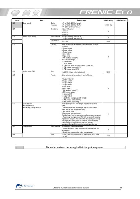
Code Name Setting range Default setting Actual setting<br />
F26 Mo<strong>to</strong>r sound<br />
Carrier 0.75 <strong>to</strong> 15 kHz (22kW or below)<br />
frequency 0.75 <strong>to</strong> 10 kHz (30kW <strong>to</strong> 75kW)<br />
0.75 <strong>to</strong> 6 kHz (90kW or above)<br />
15/10/6 kHz<br />
F27<br />
Sound <strong>to</strong>ne 0: Level 0 (Inactive)<br />
1: Level 1<br />
2: Level 2<br />
3: Level 3<br />
0<br />
F29 Analog ouptut (FMA)<br />
Mode selection 0: Output in voltage (0 <strong>to</strong> 10V DC)<br />
1: Output in current (4 <strong>to</strong> 20mA DC)<br />
0<br />
F30<br />
Output adjust.<br />
0 <strong>to</strong> 200 % 100 %<br />
F31<br />
F34<br />
F35<br />
Analog output (FMI)<br />
F37 Load selection/<br />
Au<strong>to</strong> <strong>to</strong>rque boost/<br />
Au<strong>to</strong> energy saving operation<br />
Function Select a function <strong>to</strong> be moni<strong>to</strong>red from the following 0: Output<br />
frequency<br />
2: Output current<br />
3: Output voltage<br />
4: Output <strong>to</strong>rque<br />
5: Load fac<strong>to</strong>r<br />
6: Input power<br />
7: PID feedback value (PV)<br />
9: DC link bus voltage<br />
10: Universal AO<br />
13: Mo<strong>to</strong>r output<br />
14: Calibration analog output (+10V DC / 20 mA DC)<br />
15: PID process command (SV)<br />
16: PID process output (MV)<br />
0<br />
Duty<br />
0 <strong>to</strong> 200 %: Voltage output adjustment 100 %<br />
Function Select a function <strong>to</strong> be moni<strong>to</strong>red from the following:<br />
0: Output frequency<br />
2: Output current<br />
3: Output voltage<br />
4: Output <strong>to</strong>rque<br />
5: Load fac<strong>to</strong>r<br />
6: Input power<br />
7: PID feedback value (PV)<br />
9: DC link bus voltage<br />
10: Universal AO<br />
13: Mo<strong>to</strong>r output<br />
14: Calibration analog output (20 mA DC)<br />
15: PID process command (SV)<br />
16: PID process output (MV)<br />
0: Variable <strong>to</strong>rque load increasing in proportion <strong>to</strong> square of<br />
speed<br />
1: Variable <strong>to</strong>rque load increasing in proportion <strong>to</strong> square of<br />
speed (Higher startup <strong>to</strong>rque required)<br />
2: Au<strong>to</strong>-<strong>to</strong>rque boost<br />
3: Au<strong>to</strong>-energy saving operation<br />
(Variable <strong>to</strong>rque load increasing in proportion <strong>to</strong> square of speed)<br />
4: Au<strong>to</strong>-energy saving operation (Variable <strong>to</strong>rque load increasing<br />
in proportion <strong>to</strong> square of speed; higher startup <strong>to</strong>rque required)<br />
Note: Apply this setting <strong>to</strong> a load with short acceleration time.<br />
5: Au<strong>to</strong>-energy saving operation (Au<strong>to</strong>-<strong>to</strong>rque boost)<br />
Note: Apply this setting <strong>to</strong> a load with long acceleration time.<br />
F43 Current limiter<br />
Mode selection 0: Disable (No current limiter works)<br />
1: Enable at constant speed (Disabled during acceleration and<br />
deceleration)<br />
2: Enable during acceleration and at constant speed<br />
F44<br />
Level 20 <strong>to</strong> 120 % (100% is interpreted as rated output current of the<br />
inverter)<br />
The shaded function codes are applicable <strong>to</strong> the quick setup menu<br />
Chapter 6: Function codes and application example 14<br />
0<br />
1<br />
0<br />
110 %