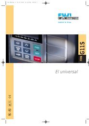
STARTING GUIDE FRENIC-Eco . FRN-F1 - Welcome to Fuji Electric
STARTING GUIDE FRENIC-Eco . FRN-F1 - Welcome to Fuji Electric
STARTING GUIDE FRENIC-Eco . FRN-F1 - Welcome to Fuji Electric

You also want an ePaper? Increase the reach of your titles
YUMPU automatically turns print PDFs into web optimized ePapers that Google loves.
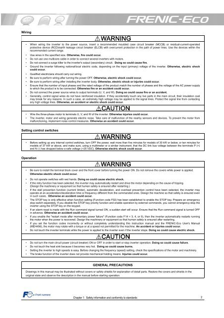
Wiring<br />
• When wiring the inverter <strong>to</strong> the power source, insert a recommended moulded case circuit breaker (MCCB) or residual-current-operated<br />
protective device (RCD)/earth leakage circuit breaker (ELCB) with overcurrent protection in the path of power lines. Use the devices within the<br />
recommended current range.<br />
• Use wires in the specified size. Otherwise, fire could occur.<br />
• Do not use one multicore cable in order <strong>to</strong> connect several inverters with mo<strong>to</strong>rs.<br />
• Do not connect a surge killer <strong>to</strong> the inverter's output (secondary) circuit. Doing so could cause fire.<br />
• Ground the inverter following national/local electric code, depending on the input (primary) voltage of the inverter. Otherwise, electric shock<br />
could occur.<br />
• Qualified electricians should carry out wiring.<br />
• Be sure <strong>to</strong> perform wiring after turning the power OFF. Otherwise, electric shock could occur.<br />
• Be sure <strong>to</strong> perform wiring after installing the inverter body. Otherwise, electric shock or injuries could occur.<br />
• Ensure that the number of input phases and the rated voltage of the product match the number of phases and the voltage of the AC power supply<br />
<strong>to</strong> which the product is <strong>to</strong> be connected. Otherwise fire or an accident could occur.<br />
• Do not connect the power source wires <strong>to</strong> output terminals (U, V, and W). Doing so could cause fire or an accident.<br />
• Generally, control signal wires do not have reinforced insulation. If they accidentally <strong>to</strong>uch any live parts in the main circuit, their insulation coat<br />
may break for any reasons. In such a case, an extremely high voltage may be applied <strong>to</strong> the signal lines. Protect the signal line from contacting<br />
any high voltage lines. Otherwise, an accident or electric shock could occur.<br />
• Wire the three-phase mo<strong>to</strong>r <strong>to</strong> terminals U, V, and W of the inverter. Otherwise injuries could occur.<br />
• The inverter, mo<strong>to</strong>r and wiring generate electric noise. Take care of malfunction of the nearby sensors and devices. To prevent the mo<strong>to</strong>r from<br />
malfunctioning, implement noise control measures. Otherwise an accident could occur.<br />
Setting control switches<br />
• Before setting up any internal control switches, turn OFF the power, wait more than five minutes for models of 30 kW or below, or ten minutes for<br />
models of 37 kW or above, and make sure, using a multimeter or a similar instrument, that the DC link bus voltage between the terminals P (+)<br />
and N (-) has dropped below a safe voltage (+25 VDC). Otherwise electric shock could occur.<br />
Operation<br />
• Be sure <strong>to</strong> install the terminal block cover and the front cover before turning the power ON. Do not remove the covers while power is applied.<br />
Otherwise electric shock could occur.<br />
• Do not operate switches with wet hands. Doing so could cause electric shock.<br />
• If the retry function has been selected, the inverter may au<strong>to</strong>matically restart and drive the mo<strong>to</strong>r depending on the cause of tripping.<br />
(Design the machinery or equipment so that human safety is ensured after restarting.)<br />
• If the stall prevention function (current limiter), au<strong>to</strong>matic deceleration, and overload prevention control have been selected, the inverter may<br />
operate at an acceleration/deceleration time or frequency different from the commanded ones. Design the machine so that safety is ensured even<br />
in such cases. Otherwise an accident could occur.<br />
• The STOP key is only effective when function setting (Function code F02) has been established <strong>to</strong> enable the STOP key. Prepare an emergency<br />
s<strong>to</strong>p switch separately. If you disable the STOP key priority function and enable operation by external commands, you cannot emergency-s<strong>to</strong>p the<br />
inverter using the STOP key on the keypad.<br />
• If an alarm reset is made with the Run command signal turned ON, a sudden start will occur. Ensure that the Run command signal is turned OFF<br />
in advance. Otherwise an accident could occur.<br />
• If you enable the "restart mode after momentary power failure" (Function code <strong>F1</strong>4 = 3, 4, or 5), then the inverter au<strong>to</strong>matically restarts running<br />
the mo<strong>to</strong>r when the power is recovered. Design the machinery or equipment so that human safety is ensured after restarting.<br />
• If you set the function codes incorrectly or without completely understanding this instruction manual and the <strong>FRENIC</strong>-<strong>Eco</strong> User's Manual<br />
(MEH456), the mo<strong>to</strong>r may rotate with a <strong>to</strong>rque or at a speed not permitted for the machine. An accident or injuries could occur.<br />
• Do not <strong>to</strong>uch the inverter terminals while the power is applied <strong>to</strong> the inverter even if the inverter s<strong>to</strong>ps. Doing so could cause electric shock.<br />
• Do not turn the main circuit power (circuit breaker) ON or OFF in order <strong>to</strong> start or s<strong>to</strong>p inverter operation. Doing so could cause failure.<br />
• Do not <strong>to</strong>uch the heat sink because it becomes very hot. Doing so could cause burns.<br />
• Setting the inverter <strong>to</strong> high speeds is easy. Before changing the frequency (speed) setting, check the specifications of the mo<strong>to</strong>r and machinery.<br />
• The brake function of the inverter does not provide mechanical holding means. Injuries could occur.<br />
GENERAL PRECAUTIONS<br />
Drawings in this manual may be illustrated without covers or safety shields for explanation of detail parts. Res<strong>to</strong>re the covers and shields in the<br />
original state and observe the description in the manual before starting operation.<br />
Chapter 1: Safety information and conformity <strong>to</strong> standards<br />
2