STARTING GUIDE FRENIC-Eco . FRN-F1 - Welcome to Fuji Electric
STARTING GUIDE FRENIC-Eco . FRN-F1 - Welcome to Fuji Electric
STARTING GUIDE FRENIC-Eco . FRN-F1 - Welcome to Fuji Electric

You also want an ePaper? Increase the reach of your titles
YUMPU automatically turns print PDFs into web optimized ePapers that Google loves.
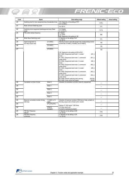
J40<br />
J41<br />
Code Name Data setting range Default setting Actual setting<br />
Switching time for mo<strong>to</strong>r sequenced s<strong>to</strong>p (Acceleration time) 0.00: Depends on the setting of F07<br />
0.01 <strong>to</strong> 3600 s<br />
0.00 s<br />
Mo<strong>to</strong>r Unmount Switching Level<br />
0 <strong>to</strong> 100 % 0 %<br />
J42 Switching mo<strong>to</strong>r sequenced start/sequenced s<strong>to</strong>p (Dead 0.0: Disable<br />
band)<br />
0.1 <strong>to</strong> 50.0 %<br />
J43 PID control startup frequency 0: Disable<br />
1 <strong>to</strong> 120Hz<br />
999: Depends on the setting of J36<br />
J44 Mo<strong>to</strong>r Mount Switching Level 0: Depends on the setting of J41<br />
1 <strong>to</strong> 100 %<br />
J45 Signal assignment <strong>to</strong>:<br />
[Y1 A/B/C] Selecting function code data assigns the corresponding function<br />
(for relay output card)<br />
<strong>to</strong> terminals [Y1A/B/C], [Y2A/B/C] and [Y3A/B/C]<br />
J46<br />
[Y2 A/B/C]<br />
J47<br />
J48<br />
J49<br />
J50<br />
J51<br />
J52<br />
Cumulative run time of mo<strong>to</strong>r<br />
[Y3 A/B/C]<br />
Mo<strong>to</strong>r 0<br />
Mo<strong>to</strong>r 1<br />
Mo<strong>to</strong>r 2<br />
Mo<strong>to</strong>r 3<br />
Mo<strong>to</strong>r 4<br />
J53 Maximum cumulative number of relay Y1 A/B/C <strong>to</strong> Y3<br />
ON times<br />
A/B/C<br />
J54<br />
[Y1], [Y2], [Y3]<br />
J55<br />
J93 PID Start Frequency<br />
(Mount)<br />
J94 PID Start Frequency<br />
(Unmount)<br />
[Y5A/C],<br />
[30A/B/C]<br />
100: Depends on the setting of E20 <strong>to</strong> E22<br />
60 (1060): Sequenced start mo<strong>to</strong>r 1, inverter-<br />
(M1_I)<br />
driven<br />
61 (1061): Sequenced start mo<strong>to</strong>r 1, commercial (M1_L)<br />
power-driven<br />
62 (1062): Sequenced start mo<strong>to</strong>r 2, inverter-<br />
(M2_I)<br />
driven<br />
63 (1063): Sequenced start mo<strong>to</strong>r 2, commercial (M2_L)<br />
power-driven<br />
64 (1064): Sequenced start mo<strong>to</strong>r 3, inverter-<br />
(M3_I)<br />
driven<br />
65 (1065): Sequenced start mo<strong>to</strong>r 3, commercial (M3_L)<br />
power-driven<br />
67 (1067): Sequenced start mo<strong>to</strong>r 4, commercial (M4_L)<br />
power-driven<br />
68 (1068): Periodic switching early warning<br />
(MCHG)<br />
69 (1069): Pump control limit signal<br />
(MLIM)<br />
Indication of cumulative run time of mo<strong>to</strong>r for replacement<br />
Indication of maximum number of ON times of relay contacts on<br />
the relay output card or those built in inverter.<br />
Display of 1.000 means 1.000 times<br />
For relay output card<br />
For built-in mechanical contacts<br />
0: Depends on the setting of J36<br />
1 <strong>to</strong> 120 Hz<br />
0: Depends on the setting of J34<br />
1 <strong>to</strong> 120 Hz<br />
Chapter 6: Function codes and application example 23<br />
0.0 %<br />
999<br />
0 %<br />
100<br />
100<br />
100<br />
---<br />
---<br />
---<br />
---<br />
---<br />
---<br />
---<br />
---<br />
0 Hz<br />
0 Hz