STARTING GUIDE FRENIC-Eco . FRN-F1 - Welcome to Fuji Electric
STARTING GUIDE FRENIC-Eco . FRN-F1 - Welcome to Fuji Electric
STARTING GUIDE FRENIC-Eco . FRN-F1 - Welcome to Fuji Electric

You also want an ePaper? Increase the reach of your titles
YUMPU automatically turns print PDFs into web optimized ePapers that Google loves.
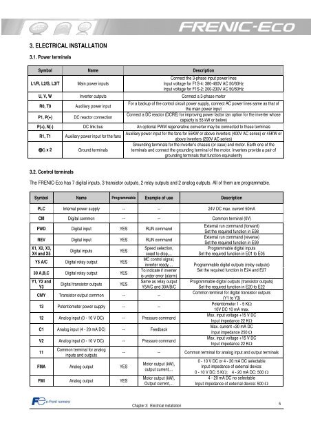
3. ELECTRICAL INSTALLATION<br />
3.1. Power terminals<br />
Symbol Name Description<br />
L1/R, L2/S, L3/T Main power inputs<br />
Connect the 3-phase input power lines<br />
Input voltage for <strong>F1</strong>S-4: 380-460V AC 50/60Hz<br />
Input voltage for <strong>F1</strong>S-2: 200-230V AC 50/60Hz<br />
U, V, W Inverter outputs Connect a 3-phase mo<strong>to</strong>r<br />
R0, T0 Auxiliary power input<br />
For a backup of the control circuit power supply, connect AC power lines same as that of<br />
the main power input<br />
P1, P(+) DC reac<strong>to</strong>r connection<br />
Connect a DC reac<strong>to</strong>r (DCRE) for improving power fac<strong>to</strong>r (an option for the inverter whose<br />
capacity is 55 kW or below)<br />
P(+), N(-) DC link bus An optional PWM regenerative converter may be connected <strong>to</strong> these terminals<br />
R1, T1 Auxiliary power input for the fans<br />
Auxiliary power input for the fans for 55KW or above inverters (400V AC series) or 45KW or<br />
above inverters (200V AC series)<br />
Grounding terminals for the inverter’s chassis (or case) and mo<strong>to</strong>r. Earth one of the<br />
G x 2 Ground terminals<br />
terminals and connect the grounding terminal of the mo<strong>to</strong>r. Inverters provide a pair of<br />
grounding terminals that function equivalently<br />
3.2. Control terminals<br />
The <strong>FRENIC</strong>-<strong>Eco</strong> has 7 digital inputs, 3 transis<strong>to</strong>r outputs, 2 relay outputs and 2 analog outputs. All of them are programmable.<br />
Symbol Name Programmable Example of use Description<br />
PLC Internal power supply -- -- 24V DC max. current 50mA<br />
CM Digital common -- -- Common terminal (0V)<br />
FWD Digital input YES RUN command<br />
REV Digital input YES RUN command<br />
X1, X2, X3,<br />
X4 and X5<br />
Digital inputs YES<br />
Y5 A/C Digital relay output YES<br />
30 A,B,C Digital relay output YES<br />
Y1, Y2 and<br />
Y3<br />
Digital transis<strong>to</strong>r outputs YES<br />
Speed selection,<br />
coast <strong>to</strong> s<strong>to</strong>p,...<br />
MC control signal,<br />
inverter ready,...<br />
To indicate if inverter<br />
is under error (alarm)<br />
Same as relay output<br />
Y5A/C and 30A/B/C<br />
CMY Transis<strong>to</strong>r output common -- --<br />
13 Potentiometer power supply -- --<br />
12 Analog input (0 - 10 V DC) -- Pressure command<br />
C1 Analog input (4 - 20 mA DC) -- Feedback<br />
V2 Analog input (0 - 10 V DC) -- Pressure command<br />
11<br />
Common terminal for analog<br />
inputs and outputs<br />
FMA Analog output YES<br />
FMI Analog output YES<br />
Chapter 3: <strong>Electric</strong>al installation<br />
External run command (forward)<br />
Set the required function in E98<br />
External run command (reverse)<br />
Set the required function in E99<br />
Programmable digital inputs<br />
Set the required function in E01 <strong>to</strong> E05<br />
Programmable digital outputs (relay outputs)<br />
Set the required function in E24 and E27<br />
Programmable digital outputs (transis<strong>to</strong>r outputs)<br />
Set the required function in E20 <strong>to</strong> E22<br />
Common terminal for digital transis<strong>to</strong>r outputs<br />
(Y1 <strong>to</strong> Y3)<br />
Potentiometer 1 - 5 KΩ<br />
10V DC 10 mA max.<br />
Max. input voltage +15 V DC<br />
Input impedance 22 KΩ<br />
Max. current +30 mA DC<br />
Input impedance 250 Ω<br />
Max. input voltage +15 V DC<br />
Input impedance 22 KΩ<br />
-- -- Common terminal for analog input and output terminals<br />
Mo<strong>to</strong>r output (kW),<br />
output current,...<br />
Mo<strong>to</strong>r output (kW),<br />
Output current,...<br />
0 - 10 V DC or 4 - 20 mA DC selectable<br />
Input impedance of external device:<br />
0 - 10 V DC: 5 KΩ; 4 - 20 mA DC: 500 Ω<br />
4 - 20 mA DC no selectable<br />
Input impedance of external device: 500 Ω<br />
5