STARTING GUIDE FRENIC-Eco . FRN-F1 - Welcome to Fuji Electric
STARTING GUIDE FRENIC-Eco . FRN-F1 - Welcome to Fuji Electric
STARTING GUIDE FRENIC-Eco . FRN-F1 - Welcome to Fuji Electric

You also want an ePaper? Increase the reach of your titles
YUMPU automatically turns print PDFs into web optimized ePapers that Google loves.
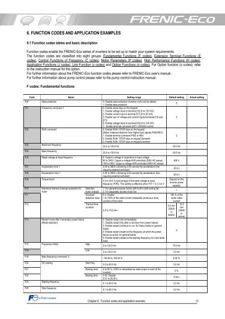
6. FUNCTION CODES AND APPLICATION EXAMPLES<br />
6.1 Function codes tables and basic description<br />
Function codes enable the <strong>FRENIC</strong>-<strong>Eco</strong> series of inverters <strong>to</strong> be set up <strong>to</strong> match your system requirements.<br />
The function codes are classified in<strong>to</strong> eight groups: Fundamental Functions (F codes), Extension Terminal Functions (E<br />
codes), Control Functions of Frequency (C codes), Mo<strong>to</strong>r Parameters (P codes), High Performance Functions (H codes),<br />
Application Functions (J codes), Link Function (y codes) and Option Functions (o codes). For Option function (o codes), refer<br />
<strong>to</strong> the instruction manual for the option.<br />
For further information about the <strong>FRENIC</strong>-<strong>Eco</strong> function codes please refer <strong>to</strong> <strong>FRENIC</strong>-<strong>Eco</strong> user's manual.<br />
For further information about pump control please refer <strong>to</strong> the pump control instruction manual.<br />
F codes: Fundamental functions<br />
Code Name Setting range Default setting Actual setting<br />
F00 Data protection 0: Disable data protection (function code can be edited)<br />
1: Enable data protection<br />
0<br />
F01 Frequency command 1 0: Enable arrow keys on the keypad<br />
1: Enable voltage input <strong>to</strong> terminal [12] (0 <strong>to</strong> 10V DC)<br />
2: Enable current input <strong>to</strong> terminal [C1] (4 <strong>to</strong> 20 mA)<br />
3: Enable sum of voltage and current inputs terminals [12] and<br />
[C1]<br />
5: Enable voltage input <strong>to</strong> terminal [V2] (0 <strong>to</strong> 10V DC)<br />
7: Enable terminal command (UP) / (DOWN) control<br />
0<br />
F02 RUN command 0: Enable RUN / STOP keys on the keypad<br />
(Mo<strong>to</strong>r rotational direction from digital input signals FWD/REV)<br />
1: Enable terminal command FWD or REV<br />
2: Enable RUN / STOP keys on keypad (forward)<br />
3: Enable RUN / STOP keys on keypad (reverse)<br />
2<br />
F03<br />
Maximum frequency<br />
25.0 <strong>to</strong> 120.0 Hz 50.0 Hz<br />
F04<br />
Base frequency<br />
25.0 <strong>to</strong> 120.0 Hz 50.0 Hz<br />
F05 Rated voltage at base frequency 0: Output a voltage in proportion <strong>to</strong> input voltage<br />
80 <strong>to</strong> 240V: Output a voltage AVR-controlled (200V AC series)<br />
160 <strong>to</strong> 500V: Output a voltage AVR-controlled (400V AC series)<br />
F07 Acceleration time 1 0.00 <strong>to</strong> 3600 s (Entering 0.00 cancels the acceleration time,<br />
requiring external soft-start)<br />
F08 Deceleration time 1 0.00 <strong>to</strong> 3600 s (Entering 0.00 cancels the deceleration time,<br />
requiring external soft-start)<br />
F09 Torque boost<br />
0.0 <strong>to</strong> 20.0 % (percentage of the rated voltage at base<br />
frequency (F05)). This setting is effective when F37 = 0,1,3 or 4<br />
<strong>F1</strong>0 Electronic thermal overload protection for Selection 1: For general-purpose mo<strong>to</strong>rs with built-in-self-cooling fan<br />
mo<strong>to</strong>r<br />
mo<strong>to</strong>r charact. 2: For separately excited mo<strong>to</strong>r fan<br />
<strong>F1</strong>1 Overload 0.0: Disable<br />
detection level 1 <strong>to</strong> 135% of the rated current (allowable continuous drive<br />
current) of the mo<strong>to</strong>r<br />
<strong>F1</strong>2<br />
Thermal time<br />
constant<br />
0.5 <strong>to</strong> 75.0 min<br />
<strong>F1</strong>4 Restart mode after momentary power failure<br />
(Mode selection)<br />
<strong>F1</strong>5<br />
<strong>F1</strong>6<br />
<strong>F1</strong>8<br />
F20<br />
Frequency limiter<br />
Bias (frequency command 1)<br />
DC braking<br />
High<br />
Low<br />
Start freq.<br />
0: Disable restart (trip immediately)<br />
1: Disable restart (trip after a recovery from power failure)<br />
3: Enable restart (continue <strong>to</strong> run, for heavy inertia or general<br />
loads)<br />
4: Enable restart (restart at the frequency at which the power<br />
failure occurred, for general loads)<br />
5: Enable restart (restart at the starting frequency, for low-inertia<br />
load)<br />
400 V<br />
20.0 s<br />
20.0 s<br />
Depend on the<br />
inverter power<br />
capacity<br />
Chapter 6: Function codes and application example 13<br />
1<br />
100 % of the<br />
mo<strong>to</strong>r rated<br />
current<br />
5.0 min<br />
(22kW<br />
or<br />
below)<br />
0 <strong>to</strong> 120.0 Hz 70.0 Hz<br />
0 <strong>to</strong> 120.0 Hz 0.0 Hz<br />
-100.00 <strong>to</strong> 100.00 % 0.00 %<br />
0.0 <strong>to</strong> 60.0 Hz 0.0 Hz<br />
F21 Braking level 0 <strong>to</strong> 60 % (100% is interpreted as rated output current of the<br />
inverter)<br />
0 %<br />
F22<br />
Braking time 0.00: Disable<br />
0.01 <strong>to</strong> 30.00 s<br />
0.00 s<br />
F23<br />
Starting frequency<br />
0.1 <strong>to</strong> 60.0 Hz 0.5 Hz<br />
F25<br />
S<strong>to</strong>p frequency<br />
0.1 <strong>to</strong> 60.0 Hz 0.2 Hz<br />
0<br />
10.0<br />
min<br />
(30kW<br />
or<br />
above)