STARTING GUIDE FRENIC-Eco . FRN-F1 - Welcome to Fuji Electric
STARTING GUIDE FRENIC-Eco . FRN-F1 - Welcome to Fuji Electric
STARTING GUIDE FRENIC-Eco . FRN-F1 - Welcome to Fuji Electric

Create successful ePaper yourself
Turn your PDF publications into a flip-book with our unique Google optimized e-Paper software.
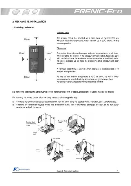
2. MECHANICAL INSTALLATION<br />
2.1 Installing the inverter<br />
10 mm *<br />
100 mm<br />
100 mm<br />
10 mm *<br />
Mounting base<br />
The inverter should be mounted on a base made of material that can<br />
withstand heat sink temperature, which can rise up <strong>to</strong> 90ºC approx. during<br />
inverter operation.<br />
Clearances<br />
Ensure that the minimum clearances indicated are maintained at all times.<br />
When installing the inverter in the enclosure of your system, take extra care<br />
with ventilation inside the enclosure as the temperature around the inverter<br />
will tend <strong>to</strong> increase. Do not install the inverter in a small enclosure with poor<br />
ventilation.<br />
* For 400V class 90kW or above a 50 mm clearance is needed instead of 10<br />
mm (left and right sides).<br />
As long as the ambient temperature is 40°C or lower, 5.5 kW or lower<br />
inverters may be mounted side-by-side without any gap between them.<br />
For others inverters, please follow the clearances needed.<br />
2.2 Removing and mounting the inverter covers (for inverters 37kW or above, please refer <strong>to</strong> user’s manual for details)<br />
For mounting the covers, please follow removing instructions in the opposite way.<br />
To remove the terminal block cover, loose the screw, hold the cover using the labelled “PULL” indication, pull it up <strong>to</strong>wards you.<br />
To remove the front cover (keypad cover), hold it with both hands, slide it downwards, disengage the latch, tilt the front cover<br />
<strong>to</strong>wards you and pull it upwards.<br />
Chapter 2: Mechanical installation<br />
4