
Create successful ePaper yourself
Turn your PDF publications into a flip-book with our unique Google optimized e-Paper software.
®<br />
Schneckenradsätze Worm and Wheel Sets Couples avec vis sans fin<br />
Bedingungen für den Einbau Design Requirements for Fitting Données pour le montage<br />
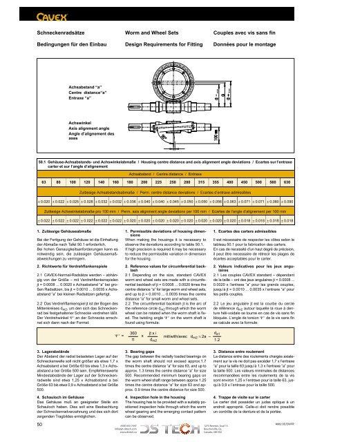
Achsabstand “a”<br />
Centre distance“a”<br />
Entraxe “a”<br />
Achswinkel<br />
Axis alignment angle<br />
Angle d’alignement des<br />
axes<br />
50.1 Gehäuse-Achsabstands- und Achswinkelabmaße / Housing centre distance and axis alignment angle deviations / Ecartes sur l’entraxe<br />
carter et sur l’angle d’alignement<br />
Achsabstand / Centre distance / Entraxe<br />
63 80 100 120 140 160 180 200 225 250 280 315 355 400 450 500 560 630<br />
Zulässige Achsabstandsabmaße / Perm. centre distance deviations / Ecartes d’entraxe admissibles<br />
± 0.020 ± 0.022 ± 0.025 ± 0.028 ± 0.032 ± 0.032 ± 0.036 ± 0.040 ± 0.040 ± 0.045 ± 0.050 ± 0.050 ± 0.056 ± 0.063 ± 0.071 ± 0.071 ± 0.080 ± 0.090<br />
Zulässige Achswinkelabmaße pro 100 mm / Perm. axis alignment angle deviations per 100 mm / Ecartes de l’angle d’alignement per 100 mm<br />
± 0.022 ± 0.022 ± 0.022 ± 0.022 ± 0.022 ± 0.022 ± 0.020 ± 0.020 ± 0.020 ± 0.020 ± 0.020 ± 0.020 ± 0.020 ± 0.020 ± 0.018 ± 0.018 ± 0.018 ± 0.018<br />
1. Zulässige Gehäuseabmaße<br />
Bei der Fertigung der Gehäuse ist die Einhaltung<br />
der Abmaße nach Tafel 50.1 erforderlich.<br />
Bei hohen Genauigkeitsanforderungen kann es<br />
notwendig sein, die zulässigen Gehäusemaßabweichungen<br />
zu verringern.<br />
2. Richtwerte für Verdrehflankenspiele<br />
2.1 CAVEX-Normal-Radsätze werden – abhängig<br />
von der Größe – mit Verdrehflankenspielen<br />
jt = 0.0008 ... 0.0020 x Achsabstand “a” bei großen<br />
Radsätzen, bis jt = 0.0010 ... 0.0035 x Achsabstand<br />
“a” bei <strong>kl</strong>einen Radsätzen gefertigt.<br />
2.2 Das Verdrehflankenspiel jt ist der Bogen des<br />
Mittenkreises d m2 , um den sich das Schneckenrad<br />
bei festgehaltener Schnecke verdrehen läßt.<br />
Der Verdrehwinkel Ψ an der Schnecke errechnet<br />
sich dann nach der Formel:<br />
1. Permissible deviations of housing dimensions<br />
When making the housings it is necessary to<br />
observe the deviations according to table 50.1.<br />
If high precision is required it may be necessary<br />
to reduce the permissible variation in dimension<br />
for the housing.<br />
2. Reference values for circumferential bac<strong>kl</strong>ash<br />
2.1 Depending on the size, standard CAVEX<br />
worm and wheel sets are made with a circumferential<br />
bac<strong>kl</strong>ash of jt = 0.0008 ... 0.0020 times the<br />
centre distance “a” for large worm and wheel sets,<br />
and up to jt = 0.0010 ... 0.0035 times the centre<br />
distance “a” for small worm and wheel sets.<br />
2.2 The circumferential bac<strong>kl</strong>ash jt is the arc of<br />
the reference circle d m2 through which the worm<br />
wheel can be rotated when the worm shaft is fixed.<br />
The twisting angle Ψ on the worm shaft is<br />
found using formula:<br />
1. Ecartes des carters admissibles<br />
Il est nécessaire de respecter les côtes selon le<br />
tableau 50.1 pour la fabrication des carters.<br />
En cas de necessité d’un haut degré de précision,<br />
il peut être necessaire de rétrecir les plages de<br />
écartes acceptables pour le carter.<br />
2. Valeurs indicatives pour les jeux angulaires<br />
2.1 Les couples CAVEX standard – dépendant<br />
de la taille – ont des jeux angulaires jt = 0.0008 ...<br />
0.0020 x l’entraxe “a” pour les grands couples,<br />
jusqu’à jt = 0.0010 ... 0.0035 x l’entraxe “a” pour<br />
les petits couples.<br />
2.2 Le jeu angulaire jt est la courbe du cercle<br />
de référence d m2 autour laquelle la roue à denture<br />
héli-voidale se tourne en cas de vis sans fin<br />
bloquée. L’angle de torsion Ψ de la vis sans fin<br />
se calcule avec la formule:<br />
Ψ =<br />
360<br />
π<br />
x<br />
jt x i<br />
d m2<br />
mit/with/avec d m2 ≈ 2a –<br />
d a1<br />
1.2<br />
3. Lagerabstände<br />
Der Abstand der radial belasteten Lager auf der<br />
Schneckenwelle soll nicht größer als etwa 1,7 x<br />
Achsabstand a bei Größe 63 bis etwa 1,3 x Achsabstand<br />
a bei Größe 500 sein. Empfehlenswerte<br />
Mindestabstände der Lager auf der Schneckenradwelle<br />
sind etwa 1,25 x Achsabstand a bei<br />
Größe 63 bis etwa 0,9 x Achsabstand a bei Größe<br />
500.<br />
4. Schauloch im Gehäuse<br />
Das Gehäuse muß an geeigneter Stelle ein<br />
Schauloch haben. Dies soll eine Beobachtung<br />
der Schneckenradverzahnung und des sich dort<br />
zeigenden Tragbildes ermöglichen.<br />
3. Bearing gaps<br />
The gap between the radially loaded bearings on<br />
the worm shaft should not exceed approx.1.7<br />
times the centre distance “a“ for size 63, and up to<br />
approx. 1.3 times the centre distance “a” for size<br />
500. Recommended minimum bearing gaps on<br />
the worm wheel shaft range between approx 1.25<br />
times the centre distance “a” for size 63 and approx.<br />
0.9 times the centre distance for size 500.<br />
4. Inspection hole in the housing<br />
The housing has to be provided with a suitably positioned<br />
inspection hole through which the worm<br />
wheel gearing and the emerging contact pattern<br />
can be observed.<br />
3. Distance entre roulement<br />
La distance entre des roulements chargés axialement<br />
sur la vis ne doit pas excéder 1,7 x l’entraxe<br />
“a” pour la taille 63 jusqu’à 1,3 x l’entraxe “a” pour<br />
la taille 500. Les valeurs minimales de distances<br />
recommandées entre les roulements de la vis<br />
sont environ 1,25 x l’entraxe pour la taille 63, jusqu’à<br />
0,9 x l’entraxe pour la taille 500.<br />
4. Trappe de visite sur le carter<br />
Le carter doit posséder un judas optique à un<br />
endroit approprié. Celle-ci doit rendre possible<br />
un contrôle de la denture et de la portée.<br />
50 (450) 655-7447<br />
1275 Newton, local 15<br />
K882 DE/EN/FR<br />
info@pt-dstech.com<br />
Boucherville, Qc,<br />
www.dstech.ca<br />
Canada, J4B 5H2