TAC Pneumatic Products Catalog
TAC Pneumatic Products Catalog
TAC Pneumatic Products Catalog

Create successful ePaper yourself
Turn your PDF publications into a flip-book with our unique Google optimized e-Paper software.
<strong>Pneumatic</strong> Liquid Flow Switch<br />
The control port opens on no flow and closes on liquid flow.<br />
Features:<br />
• Used with P/E Switch, reduces installation cost when flow sensing<br />
location is located a considerable distance from the desired electrical<br />
switching point.<br />
• If used with a DPDT P/E Switch, one circuit can be used to stop (or<br />
start) a motor, while the other circuit closes to initiate an alarm.<br />
• Paddles for 1 in., 2 in., and 3 in. pipe included.<br />
Model Chart<br />
Model No. Description<br />
N100-2511 <strong>Pneumatic</strong> liquid flow switch.<br />
Specifications<br />
Case 0.062 in. cold rolled steel finish.<br />
Cover 0.028 in. cold rolled steel.<br />
Finish Gray baked enamel.<br />
Maximum liquid pressure 150 psig (1034 kPa).<br />
Maximum liquid temperature 250�F (121�C).<br />
Minimum liquid temperature 32�F (0�C).<br />
Flow Signal passes.<br />
No flow Signal exhausts.<br />
Restrictor Requires one N100-0010, N4-32, or N100-2501.<br />
Dimensions 4-17/32 W x 4-25/32 H x 2-13/16 D (115 x 121 x 71 mm).<br />
Typical Flow Rates � GPM Required to Actuate Switch.<br />
Line Pipe Size 1 in. 1-1/4 in. 1-1/2 in. 2 in. 2-1/2 in. 3 in. 4 in. a<br />
Min. adj.<br />
Max. adj.<br />
Closes on<br />
flow incr.<br />
Opens on<br />
flow decr.<br />
Closes on<br />
flow incr.<br />
Opens on<br />
flow decr.<br />
a<br />
Flow rates for these sizes are calculated.<br />
b These GPM figures are for switch with 6 in. paddle. For 4 in. and 5 in. line pipe, the paddle is trimmed.<br />
Typical Applications<br />
4.2 5.6 7.5 13.7 17.5 27.5<br />
2.5 3.5 5.0 9.5 12.0 19.0<br />
9.3 13.3 17.7 27.0 31.0 90.0<br />
9.0 12.5 16.5 25.0 28.5 47.0<br />
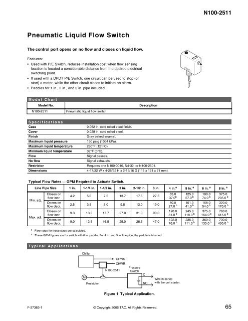
Chiller<br />
M<br />
Restrictor<br />
N100-2511<br />
CHWS<br />
CHWR<br />
Pressure<br />
Switch<br />
Figure 1 Typical Application.<br />
C<br />
NO<br />
65.0<br />
37.0 b<br />
50.0<br />
27.0 b<br />
120.0<br />
81.0 b<br />
122.0<br />
76.0 b<br />
Wire in series<br />
with the unit starter.<br />
N100-2511<br />
5 in. a 6 in. a 8 in. a<br />
125.0<br />
57.0 b<br />
101.0<br />
41.0 b<br />
245.0<br />
118.0 b<br />
235.0<br />
111.0 b<br />
190.0<br />
74.0 b<br />
158.0<br />
54.0 b<br />
375.0<br />
164.0 b<br />
360.0<br />
135.0 b<br />
375.0<br />
205.0 b<br />
320.0<br />
170.0 b<br />
760.0<br />
415.0 b<br />
730.0<br />
400.0 b<br />
F-27383-1 © Copyright 2006 <strong>TAC</strong>. All Rights Reserved. 65<br />
N100-2