Start with Moeller - Klockner Moeller Parts
Start with Moeller - Klockner Moeller Parts
Start with Moeller - Klockner Moeller Parts

Create successful ePaper yourself
Turn your PDF publications into a flip-book with our unique Google optimized e-Paper software.
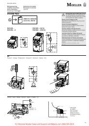
Circuit for Manual Restart<br />
L1<br />
L2<br />
L3<br />
N<br />
M<br />
3~<br />
Z1<br />
Z2<br />
T1<br />
T2<br />
C1 C2<br />
Y1 Y2<br />
A1 A2 95 97 05 07<br />
l<br />
P<br />
Reset<br />
Mode<br />
Test<br />
Reset<br />
L1 L2 L3<br />
Class<br />
Up<br />
Down<br />
~ =<br />
%<br />
5 10 15 20<br />
25 30 35 40<br />
STARTER-CAT-USA-1206 moellerNA.com B21<br />
Fault<br />
Free<br />
parameter 1<br />
Free<br />
parameter 2<br />
96 98 06 08<br />
Inputs Outputs<br />
Menu<br />
0 – 820 A<br />
Hand Auto<br />
ON OFF<br />
1) IF: internal fault<br />
ON OFF<br />
Free<br />
parameter<br />
1<br />
!<br />
> 105%<br />
IF 1)<br />
Free<br />
parameter<br />
1<br />
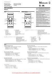
A 1 / A 2 Rated control voltage 95 / 96 NC contact for overload / thermistor<br />
T 1 / T 2 Thermistor sensor 97 / 98 NO contact for overload / thermistor<br />
C 1 / C 2 SSW core-balance transformers 05 / 06 NC contact freely assignable<br />
Y 1 / Y 2 Remote reset 07 / 08 NO contact freely assignable<br />
Switchgear and cable sizing corresponding to the respective starting inertia (CLASS)<br />
The switchgear is designed for “CLASS 10” in normal and overload operation. To ensure that the switchgear (circuit-breaker and contactor)<br />
as well as the cables are not overloaded <strong>with</strong> extended tripping times, they must be over-dimensioned accordingly. The rated operational<br />
current Ie for switchgear and cables can be calculated <strong>with</strong> the following current factor while taking the tripping class into account:<br />
Tripping Class Class 5 Class 10 Class 15 Class 20 Class 25 Class 30 Class 35 Class 40<br />
Current factor for rated operational<br />
current Ie<br />
1.00 1.00 1.22 1.41 1.58 1.73 1.89 2.00<br />
Relays <strong>with</strong> integrated sensor<br />
With the ZEV-XSW-25 to ZEV-XSW-145 push-through sensors, the motor supply leads for each phase are pushed through the respective<br />
push-through openings. On motor currents which are less than 1 A, the motor supply leads <strong>with</strong> the ZEV-XSW-25 are inserted in loops. The<br />
number of loops depends on the rated motor current involved.<br />
Number of loops n 4 3 2<br />
Rated motor current IN [A] 0.31 – 0.4 0.41 – 0.62 0.63 – 1.24<br />
Current settings on relay IE between lowest and<br />
highest value<br />
The current setting IE of the device is calculated as: IE = n x IN<br />
[A] 1.24 – 1.6 1.23 – 1.86 1.26 – 2.48<br />
Class<br />
e<br />
Reset<br />
For Immediate Delivery call KM<strong>Parts</strong>.com at (866) 595-9616<br />
Electronic Overload Relays<br />
!<br />
> 105%<br />
IF 1)<br />
Selection Aids<br />
B<br />
Motor Protection