- Page 1:
International Catalogue
- Page 4 and 5:
Good reasons to choose fischer A br
- Page 6 and 7:
Innovations to inspire professional
- Page 8 and 9:
Products - Quick overview Selection
- Page 10 and 11:
Products - Quick overview Selection
- Page 12 and 13:
Products - Detailed overview Select
- Page 14 and 15:
Products - Detailed overview Select
- Page 16 and 17:
Products - Detailed overview Select
- Page 18 and 19:
Products - Detailed overview Select
- Page 20 and 21:
Products - Detailed overview Select
- Page 22 and 23:
Products - Detailed overview Select
- Page 24 and 25:
Application selection guide Selecti
- Page 26 and 27:
Application selection guide Selecti
- Page 28 and 29:
Application selection guide Selecti
- Page 30 and 31:
Application selection guide Selecti
- Page 32 and 33:
Application selection guide Selecti
- Page 34 and 35:
Application selection guide Selecti
- Page 36 and 37:
Application selection guide Selecti
- Page 38 and 39:
Application selection guide Selecti
- Page 40 and 41:
Chemical fixings 40
- Page 42 and 43:
Chemical fixings Range of chemical
- Page 44 and 45:
Chemical fixings Range of chemical
- Page 46 and 47:
Highbond-System FHB II Chemical fix
- Page 48 and 49:
Highbond-System FHB II Chemical fix
- Page 50 and 51:
Highbond anchor FHB II-A S Chemical
- Page 52 and 53:
Highbond anchor FHB II-A S Chemical
- Page 54 and 55:
Highbond anchor FHB II-A L Chemical
- Page 56 and 57:
Highbond anchor FHB II-A L Chemical
- Page 58 and 59:
Resin anchor R with threaded rod RG
- Page 60 and 61:
Resin anchor R with threaded rod RG
- Page 62 and 63:
Resin anchor R with threaded rod RG
- Page 64 and 65:
Resin anchor R with RG MI Chemical
- Page 66 and 67:
Resin anchor R with RG MI Chemical
- Page 68 and 69:
Injection mortar FIS EM Chemical fi
- Page 70 and 71:
Injection mortar FIS EM Chemical fi
- Page 72 and 73:
Injection mortar FIS V Chemical fix
- Page 74 and 75:
Injection mortar FIS V Chemical fix
- Page 76 and 77:
Injection mortar FIS VW Chemical fi
- Page 78 and 79:
Injection mortar FIS VW Chemical fi
- Page 80 and 81:
Injection mortar FIS VS Chemical fi
- Page 82 and 83:
Injection mortar FIS VS Chemical fi
- Page 84 and 85:
Injection mortar FIS VT Chemical fi
- Page 86 and 87:
Injection mortar FIS P Chemical fix
- Page 88 and 89:
Injection mortar FIS P Chemical fix
- Page 90 and 91:
Injection for cracked concrete with
- Page 92 and 93:
Injection for cracked concrete with
- Page 94 and 95:
Injection for cracked concrete with
- Page 96 and 97:
Injection for cracked concrete with
- Page 98 and 99:
Injection non-cracked concrete with
- Page 100 and 101:
Injection non-cracked concrete with
- Page 102 and 103:
Injection non-cracked concrete with
- Page 104 and 105:
Injection non-cracked concrete with
- Page 106 and 107:
Injection in solid brick masonry Ch
- Page 108 and 109:
Injection in solid brick masonry Ch
- Page 110 and 111:
Injection in solid brick masonry Ch
- Page 112 and 113:
Injection in perforated brick mason
- Page 114 and 115:
Injection in perforated brick mason
- Page 116 and 117:
Push-through installation in masonr
- Page 118 and 119:
Push-through installation in masonr
- Page 120 and 121:
Injection for aerated concrete with
- Page 122 and 123:
Injection for aerated concrete with
- Page 124 and 125:
Rebar connections Chemical fixings
- Page 126 and 127:
Rebar connections Chemical fixings
- Page 128 and 129:
Highbond anchor dynamic FHB dyn Che
- Page 130 and 131:
Highbond anchor dynamic FHB dyn Che
- Page 132 and 133:
UMV multicone dynamic bonded anchor
- Page 134 and 135:
UMV multicone dynamic bonded anchor
- Page 136 and 137:
Stand-off installation Thermax Chem
- Page 138 and 139:
Stand-off installation Thermax Chem
- Page 140 and 141:
Remedial wall tie VBS 8 Chemical fi
- Page 142 and 143:
Remedial wall tie mechanical VBS-M
- Page 144 and 145:
Weather facing reconstruction syste
- Page 146 and 147:
Can System FCS Chemical fixings The
- Page 148 and 149:
fill & fix injection fixing Chemica
- Page 150 and 151:
High performance steel anchors 150
- Page 152 and 153:
High performance steel anchors Rang
- Page 154 and 155:
Bolt anchor FAZ II High performance
- Page 156 and 157:
Bolt anchor FAZ II High performance
- Page 158 and 159:
Bolt anchor FAZ II GS High performa
- Page 160 and 161:
Bolt anchor FAZ II GS High performa
- Page 162 and 163:
High performance anchor FH II High
- Page 164 and 165:
High performance anchor FH II High
- Page 166 and 167:
High performance anchor FH II High
- Page 168 and 169:
ZYKON undercut anchor FZA High perf
- Page 170 and 171:
ZYKON undercut anchor FZA High perf
- Page 172 and 173:
ZYKON undercut anchor FZA High perf
- Page 174 and 175:
ZYKON undercut anchor FZA-I High pe
- Page 176 and 177:
ZYKON hammerset anchor FZEA II High
- Page 178 and 179:
ZYKON hammerset anchor FZEA II High
- Page 180 and 181:
Concrete screw FBS High performance
- Page 182 and 183:
Concrete screw FBS High performance
- Page 184 and 185:
Concrete screw FBS High performance
- Page 186 and 187:
Hammerset anchor EA II High perform
- Page 188 and 189:
Hammerset anchor EA II High perform
- Page 190 and 191:
Nail anchor FNA II High performance
- Page 192 and 193:
Nail anchor FNA II High performance
- Page 194 and 195:
Ceiling nail FDN High performance s
- Page 196 and 197:
Bolt anchor FBN II High performance
- Page 198 and 199:
Bolt anchor FBN II High performance
- Page 200 and 201:
Bolt anchor FBN II GS High performa
- Page 202 and 203:
Bolt anchor EXA High performance st
- Page 204 and 205:
Bolt anchor EXA High performance st
- Page 206 and 207:
Heavy-duty anchor TA M High perform
- Page 208 and 209:
Heavy-duty anchor TA M High perform
- Page 210 and 211:
Heavy-duty anchor TA M-T High perfo
- Page 212 and 213:
Sleeve anchor FSA High performance
- Page 214 and 215:
Fixing set for diamond drills FDBB
- Page 216 and 217:
Wall screw MR High performance stee
- Page 218 and 219:
Hollow-ceiling anchor FHY High perf
- Page 220 and 221:
Hollow-ceiling anchor FHY High perf
- Page 222 and 223:
Frame fixings / Stand-off installat
- Page 224 and 225:
Frame fixings / Stand-off installat
- Page 226 and 227:
Frame fixing SXR Frame fixings / St
- Page 228 and 229:
Frame fixing SXR Frame fixings / St
- Page 230 and 231:
Frame fixing SXR Frame fixings / St
- Page 232 and 233:
Universal frame fixing FUR Frame fi
- Page 234 and 235:
Universal frame fixing FUR Frame fi
- Page 236 and 237:
Universal frame fixing FUR Frame fi
- Page 238 and 239:
Frame fixing SXS Frame fixings / St
- Page 240 and 241:
Frame fixing SXS Frame fixings / St
- Page 242 and 243:
Hammerfix N Frame fixings / Stand-o
- Page 244 and 245:
Hammerfix N Frame fixings / Stand-o
- Page 246 and 247:
Nail sleeve FNH Frame fixings / Sta
- Page 248 and 249:
Window frame fixing F-S Frame fixin
- Page 250 and 251:
Metal frame fixing F-M Frame fixing
- Page 252 and 253:
Window frame screws FFSZ and FFS Fr
- Page 254 and 255:
Window frame screws FFSZ and FFS Fr
- Page 256 and 257:
Adjustable fixing S10J Frame fixing
- Page 258 and 259:
Self-drilling adjustable screw JUSS
- Page 260 and 261:
Universal spacing screw ASL Frame f
- Page 262 and 263:
Stand-off installation Thermax 8 /
- Page 264 and 265:
Stand-off installation Thermax 12 /
- Page 266 and 267:
Stand-off installation Thermax 12 /
- Page 268 and 269:
Stand-off installation Thermax 12 /
- Page 270 and 271:
Remedial wall tie mechanical VBS-M
- Page 272 and 273:
Remedial wall tie VBS 8 Frame fixin
- Page 274 and 275:
General fixings 274
- Page 276 and 277:
General fixings Range of general fi
- Page 278 and 279:
Universal plug UX General fixings T
- Page 280 and 281:
Expansion plug SX General fixings T
- Page 282 and 283:
Expansion plug SX General fixings T
- Page 284 and 285:
Expansion plug S General fixings TE
- Page 286 and 287:
Metal expansion anchor FMD General
- Page 288 and 289:
Expansion plug M-S General fixings
- Page 290 and 291:
Anchor M General fixings The powerf
- Page 292 and 293:
Brass fixing MS General fixings The
- Page 294 and 295:
Aircrete anchor GB General fixings
- Page 296 and 297:
Turbo aircrete anchor FTP K General
- Page 298 and 299:
Turbo aircrete anchor FTP M General
- Page 300 and 301:
Brass fixing PA 4 General fixings T
- Page 302 and 303:
Balcony cladding fixing P9K General
- Page 304 and 305:
Stair-tread fixing TB / TBB General
- Page 306 and 307:
Doorstop TS General fixings The ins
- Page 308 and 309:
Cavity fixings 308
- Page 310 and 311:
Metal cavity fixing HM Cavity fixin
- Page 312 and 313:
Gravity- and spring-toggle K, KD, K
- Page 314 and 315:
Gravity- and spring-toggle K, KD, K
- Page 316 and 317:
Board fixing PD Cavity fixings TECH
- Page 318 and 319:
Plasterboard fixing GK Cavity fixin
- Page 320 and 321:
Plasterboard fixing metal GKM Cavit
- Page 322 and 323:
Electrical fixings 322
- Page 324 and 325:
ClipFix plus LS/ES/ZS Electrical fi
- Page 326 and 327:
ClipFix plus SD Electrical fixings
- Page 328 and 329:
Cable clasp KB Electrical fixings T
- Page 330 and 331:
Cable harness SHA Electrical fixing
- Page 332 and 333:
Pipe clip RC Electrical fixings The
- Page 334 and 335:
Pipe clip FC Electrical fixings The
- Page 336 and 337:
Saddle clip SCH Electrical fixings
- Page 338 and 339:
Nail clip NS / MNS Electrical fixin
- Page 340 and 341:
Nail disc NSB Electrical fixings Th
- Page 342 and 343:
Spacer pipe clamp AM Electrical fix
- Page 344 and 345:
Conduit clip BSM Electrical fixings
- Page 346 and 347:
Impact nail ED Electrical fixings F
- Page 348 and 349:
Cable tie BN / UBN Electrical fixin
- Page 350 and 351:
Wireclip WIC Electrical fixings Inf
- Page 352 and 353:
Sanitary fixings 352
- Page 354 and 355:
Sanitary fixings for board material
- Page 356 and 357:
Ceramic fixings Sanitary fixings Co
- Page 358 and 359:
Wash basin and urinal fixings Sanit
- Page 360 and 361:
Wash basin and urinal fixings Sanit
- Page 362 and 363:
Scaffold and eye screw fixings 362
- Page 364 and 365:
Scaffold anchoring GS 12 + plug Sca
- Page 366 and 367:
Scaffold anchoring FI G Scaffold an
- Page 368 and 369:
Eye screw GS Scaffold and eye screw
- Page 370 and 371:
Ring nut RI Scaffold and eye screw
- Page 372 and 373:
Insulation fixings / Façade fixing
- Page 374 and 375:
Insulation support DHK Insulation f
- Page 376 and 377:
Insulation support DHM Insulation f
- Page 378 and 379:
Render fixing DIPK Insulation fixin
- Page 380 and 381:
Render fixing FIF-K Insulation fixi
- Page 382 and 383:
Render fixing FIF-S Insulation fixi
- Page 384 and 385:
Insulation discs Insulation fixings
- Page 386 and 387:
Holding clamp DVN Insulation fixing
- Page 388 and 389:
Retaining disc with screw DHT S Ins
- Page 390 and 391:
Insulation fixing FID Insulation fi
- Page 392 and 393:
Insulation disc FATB Insulation fix
- Page 394 and 395:
Foams, Sealants 394
- Page 396 and 397:
One-component gun foam PUP B2 Foams
- Page 398 and 399:
One-component gun foam PUBS B2 Foam
- Page 400 and 401:
One-component gun foam PUFS B1 Foam
- Page 402 and 403:
One-component rapid installation fo
- Page 404 and 405:
2-component fixing foam Foams, Seal
- Page 406 and 407: Accessories Foams, Sealants PU-clea
- Page 408 and 409: Sanitary silicone DSSI Foams, Seala
- Page 410 and 411: Premium high temperature silicone D
- Page 412 and 413: Roof and wall silicone DBSI Foams,
- Page 414 and 415: Premium B1 silicone DFS Foams, Seal
- Page 416 and 417: Acrylic sealant DA Foams, Sealants
- Page 418 and 419: Premium ventilation duct sealant DL
- Page 420 and 421: Roof sealing compound DD Foams, Sea
- Page 422 and 423: Sealant selection matrix Foams, Sea
- Page 424 and 425: Adhesives 424
- Page 426 and 427: Assembly adhesive MK Adhesives The
- Page 428 and 429: All-round adhesive gluing and seali
- Page 430 and 431: Drills and bits 430
- Page 432 and 433: Hammer drill bit SDS Plus IV Quattr
- Page 434 and 435: Hammer drill bit SDS Plus II Pointe
- Page 436 and 437: Hammer drill bit SDS Plus II Pointe
- Page 438 and 439: Hammer drill bit SDS Max II / SDS M
- Page 440 and 441: Profi-bit FPB Drills and bits The e
- Page 442 and 443: Profi-bit FPB Drills and bits TECHN
- Page 444 and 445: Diamond bit FDB Drills and bits TEC
- Page 446 and 447: Stainless steel bit FSB Drills and
- Page 448 and 449: Bit holder FBH Drills and bits The
- Page 450 and 451: Basic Knowledge of Fastening Techno
- Page 452 and 453: Basic Knowledge of Fastening Techno
- Page 454 and 455: Basic Knowledge of Fastening Techno
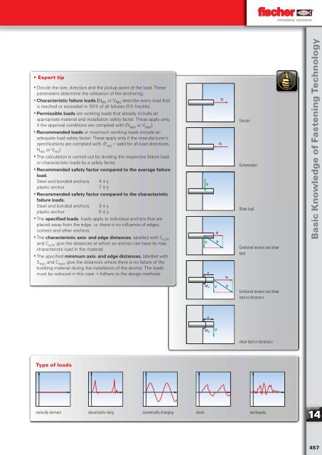
- Page 458 and 459: Basic Knowledge of Fastening Techno
- Page 460 and 461: Basic Knowledge of Fastening Techno
- Page 462 and 463: Basic Knowledge of Fastening Techno
- Page 464 and 465: Basic Knowledge of Fastening Techno
- Page 466 and 467: Basic Knowledge of Fastening Techno
- Page 468 and 469: Basic Knowledge of Fastening Techno
- Page 470 and 471: Worldwide Presence Service fischer
- Page 472 and 473: Service Training courses & seminars
- Page 474 and 475: Borderless Services Service fischer
- Page 476 and 477: Borderless Services Service fischer
- Page 478 and 479: Service Borderless Services 478
- Page 480: 06/2012 Contacts fischerwerke GmbH


