Chapter 3 Decision Support Model (IUWS-DSM) - Tubdok
Chapter 3 Decision Support Model (IUWS-DSM) - Tubdok
Chapter 3 Decision Support Model (IUWS-DSM) - Tubdok

You also want an ePaper? Increase the reach of your titles
YUMPU automatically turns print PDFs into web optimized ePapers that Google loves.
42 New Conception and <strong>Decision</strong> <strong>Support</strong> <strong>Model</strong> for <strong>IUWS</strong><br />
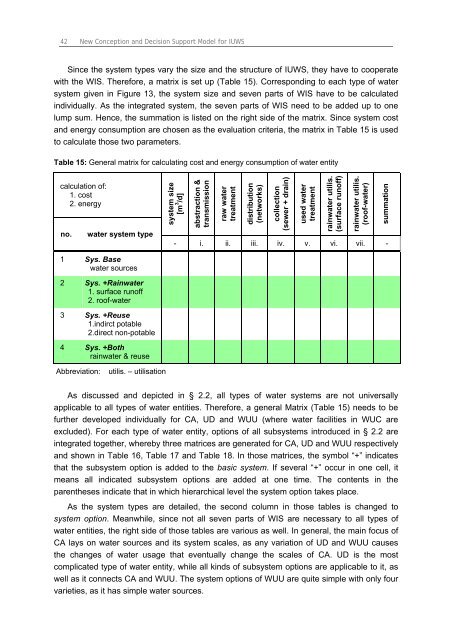
Since the system types vary the size and the structure of <strong>IUWS</strong>, they have to cooperate<br />
with the WIS. Therefore, a matrix is set up (Table 15). Corresponding to each type of water<br />
system given in Figure 13, the system size and seven parts of WIS have to be calculated<br />
individually. As the integrated system, the seven parts of WIS need to be added up to one<br />
lump sum. Hence, the summation is listed on the right side of the matrix. Since system cost<br />
and energy consumption are chosen as the evaluation criteria, the matrix in Table 15 is used<br />
to calculate those two parameters.<br />
Table 15: General matrix for calculating cost and energy consumption of water entity<br />
calculation of:<br />
1. cost<br />
2. energy<br />
no. water system type<br />
1 Sys. Base<br />
water sources<br />
2 Sys. +Rainwater<br />
1. surface runoff<br />
2. roof-water<br />
3 Sys. +Reuse<br />
1.indirct potable<br />
2.direct non-potable<br />
4 Sys. +Both<br />
rainwater & reuse<br />
Abbreviation: utilis. – utilisation<br />
system size<br />
[m 3 /d]<br />
abstraction &<br />
transmission<br />
raw water<br />
treatment<br />
distribution<br />
(networks)<br />
collection<br />
(sewer + drain)<br />
used water<br />
treatment<br />
rainwater utilis.<br />
(surface runoff)<br />
rainwater utilis.<br />
(roof-water)<br />
- i. ii. iii. iv. v. vi. vii. -<br />
As discussed and depicted in § 2.2, all types of water systems are not universally<br />
applicable to all types of water entities. Therefore, a general Matrix (Table 15) needs to be<br />
further developed individually for CA, UD and WUU (where water facilities in WUC are<br />
excluded). For each type of water entity, options of all subsystems introduced in § 2.2 are<br />
integrated together, whereby three matrices are generated for CA, UD and WUU respectively<br />
and shown in Table 16, Table 17 and Table 18. In those matrices, the symbol “+” indicates<br />
that the subsystem option is added to the basic system. If several “+” occur in one cell, it<br />
means all indicated subsystem options are added at one time. The contents in the<br />
parentheses indicate that in which hierarchical level the system option takes place.<br />
As the system types are detailed, the second column in those tables is changed to<br />
system option. Meanwhile, since not all seven parts of WIS are necessary to all types of<br />
water entities, the right side of those tables are various as well. In general, the main focus of<br />
CA lays on water sources and its system scales, as any variation of UD and WUU causes<br />
the changes of water usage that eventually change the scales of CA. UD is the most<br />
complicated type of water entity, while all kinds of subsystem options are applicable to it, as<br />
well as it connects CA and WUU. The system options of WUU are quite simple with only four<br />
varieties, as it has simple water sources.<br />
summation