Chapter 3 Decision Support Model (IUWS-DSM) - Tubdok
Chapter 3 Decision Support Model (IUWS-DSM) - Tubdok
Chapter 3 Decision Support Model (IUWS-DSM) - Tubdok

You also want an ePaper? Increase the reach of your titles
YUMPU automatically turns print PDFs into web optimized ePapers that Google loves.
80 New Conception and <strong>Decision</strong> <strong>Support</strong> <strong>Model</strong> for <strong>IUWS</strong><br />
3.5.1 Water usage<br />
The management of water usage is always considered in the first place as it eventually<br />
affects the sizes of WIS. In the hierarchy, the variation of water amount in inferior water<br />
entities will affect the superior water entities. As demonstrated in Figure 22, the management<br />
of water usage starts from WUC, followed by WUU, UD, and finally CA. As discussed in §<br />
2.2.1, one water end-user can have several water usage scenarios, which represent different<br />
conditions. In order to demonstrate the way to manage the water usage, a fictitious example<br />
with one of its water usage scenarios is implemented. Since WUC has the same structure<br />
and functions as WUU, it is skipped in the example. Thereby, it starts from WUU.<br />
In WUU, the water usage is determined based on EUWUP, whereby the possible water<br />
sources for sufficing the water demand are determined. There can be four options of water<br />
source in WUU (see Table 18 in § 2.3.1):<br />
1. only external source, i.e. from UD; as WUU: ext.src.<br />
2. add roof-water utilisation system; as WUU: +rf.wa.<br />
3. add direct non-potable water reuse system; as WUU: +drct.reuse<br />
4. add both roof-water and direct reuse systems. as WUU: +both<br />
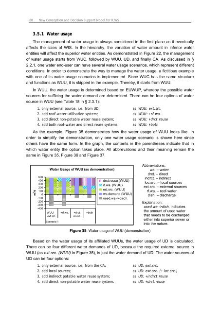
As the example, Figure 35 demonstrates how the water usage of WUU looks like. In<br />
order to simplify the demonstration, only one water usage scenario is shown here since<br />
others have the same form. In the graph, the contents in the parentheses indicate that in<br />
which water entity the option takes place. All abbrevations and their meaning remain the<br />
same in Figure 35, Figure 36 and Figure 37.<br />
m 3 /d<br />
500<br />
400<br />
300<br />
200<br />
100<br />
0<br />
-100<br />
-200<br />
-300<br />
-400<br />
Water Usage of WUU (as demonstration)<br />
WUU:<br />
ext.src.<br />
Scenario 1<br />
+rf.wa. +drct.<br />
reuse<br />
+both<br />
drct.reuse (WUU)<br />
rf.wa. (WUU)<br />
ext.src. (WUU)<br />
wa.demand (WUU)<br />
used.wa.->disch.<br />
Figure 35: Water usage of WUU (demonstration)<br />
Abbreviations:<br />
wa. – water<br />
drct. – direct<br />
indrct. – indirect<br />
loc.src. – local sources<br />
ext.src. – external sources<br />
rf.wa. – roof-water<br />
dish. – discharge<br />
Explanation:<br />
used.wa.->dish. indicates<br />
the amount of used water<br />
that needs to be discharged<br />
either into superior sewer or<br />
into the nature.<br />
Based on the water usage of its affiliated WUUs, the water usage of UD is calculated.<br />
There can be four different water demands of UD, becasue the required external source in<br />
WUU (as ext.src. (WUU) in Figure 35), is just the water demand of UD. The water sources of<br />
UD can be four options:<br />
1. only external source, i.e. from the CA; as UD: ext.src.<br />
2. add local sources; as UD: ext.src. (+ loc.src.)<br />
3. add indirect potable water reuse system; as UD: +indrct.reuse<br />
4. add direct non-potable water reuse system. as UD: +drct.reuse