Chapter 3 Decision Support Model (IUWS-DSM) - Tubdok
Chapter 3 Decision Support Model (IUWS-DSM) - Tubdok
Chapter 3 Decision Support Model (IUWS-DSM) - Tubdok

Create successful ePaper yourself
Turn your PDF publications into a flip-book with our unique Google optimized e-Paper software.
46 New Conception and <strong>Decision</strong> <strong>Support</strong> <strong>Model</strong> for <strong>IUWS</strong><br />
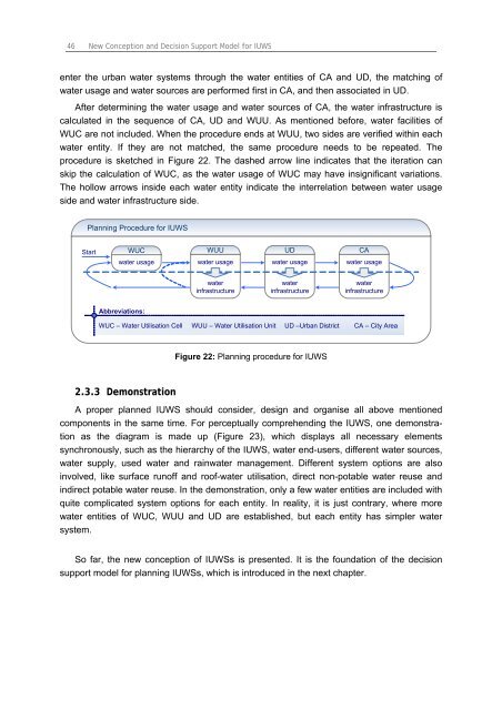
enter the urban water systems through the water entities of CA and UD, the matching of<br />
water usage and water sources are performed first in CA, and then associated in UD.<br />
After determining the water usage and water sources of CA, the water infrastructure is<br />
calculated in the sequence of CA, UD and WUU. As mentioned before, water facilities of<br />
WUC are not included. When the procedure ends at WUU, two sides are verified within each<br />
water entity. If they are not matched, the same procedure needs to be repeated. The<br />
procedure is sketched in Figure 22. The dashed arrow line indicates that the iteration can<br />
skip the calculation of WUC, as the water usage of WUC may have insignificant variations.<br />
The hollow arrows inside each water entity indicate the interrelation between water usage<br />
side and water infrastructure side.<br />
Planning Procedure for <strong>IUWS</strong><br />
Start<br />
WUC<br />
water usage<br />
Abbreviations:<br />
WUU<br />
water usage<br />
water<br />
infrastructure<br />
UD<br />
water usage<br />
water<br />
infrastructure<br />
CA<br />
water usage<br />
water<br />
infrastructure<br />
WUC – Water Utilisation Cell WUU – Water Utilisation Unit UD –Urban District CA – City Area<br />
2.3.3 Demonstration<br />
Figure 22: Planning procedure for <strong>IUWS</strong><br />
A proper planned <strong>IUWS</strong> should consider, design and organise all above mentioned<br />
components in the same time. For perceptually comprehending the <strong>IUWS</strong>, one demonstration<br />
as the diagram is made up (Figure 23), which displays all necessary elements<br />
synchronously, such as the hierarchy of the <strong>IUWS</strong>, water end-users, different water sources,<br />
water supply, used water and rainwater management. Different system options are also<br />
involved, like surface runoff and roof-water utilisation, direct non-potable water reuse and<br />
indirect potable water reuse. In the demonstration, only a few water entities are included with<br />
quite complicated system options for each entity. In reality, it is just contrary, where more<br />
water entities of WUC, WUU and UD are established, but each entity has simpler water<br />
system.<br />
So far, the new conception of <strong>IUWS</strong>s is presented. It is the foundation of the decision<br />
support model for planning <strong>IUWS</strong>s, which is introduced in the next chapter.