pdf (2140k) - Adcon Engineering Co
pdf (2140k) - Adcon Engineering Co
pdf (2140k) - Adcon Engineering Co

Create successful ePaper yourself
Turn your PDF publications into a flip-book with our unique Google optimized e-Paper software.
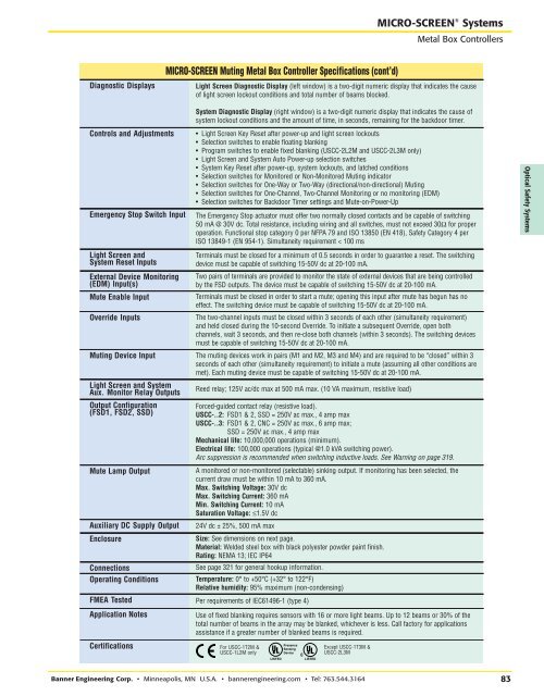
RRMICRO-SCREEN ® SystemsMetal Box <strong>Co</strong>ntrollersMICRO-SCREEN Muting Metal Box <strong>Co</strong>ntroller Specifications (cont’d)Diagnostic DisplaysLight Screen Diagnostic Display (left window) is a two-digit numeric display that indicates the causeof light screen lockout conditions and total number of beams blocked.System Diagnostic Display (right window) is a two-digit numeric display that indicates the cause ofsystem lockout conditions and the amount of time, in seconds, remaining for the backdoor timer.<strong>Co</strong>ntrols and AdjustmentsEmergency Stop Switch Input• Light Screen Key Reset after power-up and light screen lockouts•Selection switches to enable floating blanking• Program switches to enable fixed blanking (USCC-2L2M and USCC-2L3M only)• Light Screen and System Auto Power-up selection switches• System Key Reset after power-up, system lockouts, and latched conditions• Selection switches for Monitored or Non-Monitored Muting indicator• Selection switches for One-Way or Two-Way (directional/non-directional) Muting• Selection switches for One-Channel, Two-Channel Monitoring or no monitoring (EDM)• Selection switches for Backdoor Timer settings and Mute-on-Power-UpThe Emergency Stop actuator must offer two normally closed contacts and be capable of switching50 mA @ 30V dc. Total resistance, including wiring and all switches, must not exceed 30Ω for properoperation. Functional stop category 0 per NFPA 79 and ISO 13850 (EN 418), Safety Category 4 perISO 13849-1 (EN 954-1). Simultaneity requirement < 100 msOptical Safety SystemsLight Screen andSystem Reset InputsExternal Device Monitoring(EDM) Input(s)Mute Enable InputOverride InputsTerminals must be closed for a minimum of 0.5 seconds in order to guarantee a reset. The switchingdevice must be capable of switching 15-50V dc at 20-100 mA.Two pairs of terminals are provided to monitor the state of external devices that are being controlledby the FSD outputs. The device must be capable of switching 15-50V dc at 20-100 mA.Terminals must be closed in order to start a mute; opening this input after mute has begun has noeffect. The switching device must be capable of switching 15-50V dc at 20-100 mA.The two-channel inputs must be closed within 3 seconds of each other (simultaneity requirement)and held closed during the 10-second Override. To initiate a subsequent Override, open bothchannels, wait 3 seconds, and then re-close both channels (within 3 seconds). The switching devicesmust be capable of switching 15-50V dc at 20-100 mA.Muting Device Input The muting devices work in pairs (M1 and M2, M3 and M4) and are required to be “closed” within 3seconds of each other (simultaneity requirement) to initiate a mute (assuming all other conditions aremet). Each muting device must be capable of switching 15-50V dc at 20-100 mA.Light Screen and SystemAux. Monitor Relay OutputsOutput <strong>Co</strong>nfiguration(FSD1, FSD2, SSD)Mute Lamp OutputAuxiliary DC Supply OutputEnclosure<strong>Co</strong>nnectionsOperating <strong>Co</strong>nditionsReed relay; 125V ac/dc max at 500 mA max. (10 VA maximum, resistive load)Forced-guided contact relay (resistive load).USCC-..2: FSD1 & 2, SSD = 250V ac max., 4 amp maxUSCC-..3: FSD1 & 2, CNC = 250V ac max., 6 amp max;SSD = 250V ac max., 4 amp maxMechanical life: 10,000,000 operations (minimum).Electrical life: 100,000 operations (typical @1.0 kVA switching power).Arc suppression is recommended when switching inductive loads. See Warning on page 319.A monitored or non-monitored (selectable) sinking output. If monitoring has been selected, thecurrent draw must be within 10 mA to 360 mA.Max. Switching Voltage: 30V dcMax. Switching Current: 360 mAMin. Switching Current: 10 mASaturation Voltage: ≤1.5V dc24V dc ± 25%, 500 mA maxSize: See dimensions on next page.Material: Welded steel box with black polyester powder paint finish.Rating: NEMA 13; IEC IP64See page 321 for general hookup information.Temperature: 0° to +50°C (+32° to 122°F)Relative humidity: 95% maximum (non-condensing)FMEA Tested Per requirements of IEC61496-1 (type 4)Application NotesUse of fixed blanking requires sensors with 16 or more light beams. Up to 12 beams or 30% of thetotal number of beams in the array may be blanked, whichever is less. Call factory for applicationsassistance if a greater number of blanked beams is required.CertificationsFor USCC-1T2M &USCC-1L2M onlyPresenceSensingDeviceExcept USCC-1T3M &USCC-2L3MBanner <strong>Engineering</strong> <strong>Co</strong>rp. • Minneapolis, MN U.S.A. • bannerengineering.com • Tel: 763.544.316483