pdf (2140k) - Adcon Engineering Co
pdf (2140k) - Adcon Engineering Co
pdf (2140k) - Adcon Engineering Co

Create successful ePaper yourself
Turn your PDF publications into a flip-book with our unique Google optimized e-Paper software.
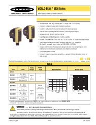
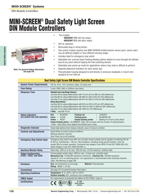
RRMINI-SCREEN ® SystemsDIN Module <strong>Co</strong>ntrollersOptical Safety SystemsMINI-SCREEN ® Dual Safety Light ScreenDIN Module <strong>Co</strong>ntrollersNote: For general hookup information,see page 341.• Two models:- MDSDINT-1T2 with trip output- MDSDINT-1L2 with latch output• 24V dc operation• Removable plug-in wiring blocks• One control module requires two MINI-SCREEN emitter/receiver sensor pairs; sensor pairsmay be different heights or have different sensing ranges• Includes input for emergency stop switch• Selectable one- and two-beam floating blanking allows objects to move through the definedarea at any point without tripping the final switching devices• Selectable auto power-up mode for applications where a key reset is difficult to perform• Separate alignment indicators for each sensor pair• Polycarbonate housing designed to bolt directly to enclosure backplate or mount ontostandard 35 mm DIN railSystem Power RequirementsFuse RatingResponse TimeStatus Indicators(on control box and receiver)Diagnostic Indicator<strong>Co</strong>ntrols and AdjustmentsEmergency Stop Switch InputAuxiliary Monitor RelayOutput <strong>Co</strong>nfiguration(FSD1, FSD2, and SSD)24V dc ±15%, 10% maximum ripple, 2.5 amps max.3 amp, 250V (3AG or 5x20mm slow blow)Standard and Long-Range Sensors:Less than 48 ms using emitter/receiver with 114 mm (4.5") to 406 mm (16") defined areaLess than 60 ms using emitter/receiver with 508 mm (20") to 813 mm (32") defined areaLess than 72 ms using emitter/receiver with 914 mm (36") to 1219 mm (48") defined areaHeavy Duty Sensors:Less than 48 ms using emitter/receiver with 610 mm (24") to 813 mm (32") defined areaLess than 60 ms using emitter/receiver with 1016 mm (40") to 1626 mm (64") defined areaLess than 72 ms using emitter/receiver with 1829 mm (72") defined areaE-Stop: Less than 15 msRed = BLOCKED Flashing red = LOCKOUTGreen = CLEAR Flashing green = BLANKING ONYellow = RESET Double-flashing yellow = Waiting for Power-up Key ResetSingle-flashing yellow = ALIGNMENT. Flash rate increases with the number of sensing beams“made”, solid yellow when aligned and defined area is clear.Single-digit alphanumeric display indicates cause of lockout condition.Keyed Reset of system lockout conditionsBlanking selection switchesAuto Power Up on-off switchesEmergency stop switch must offer two normally closed contacts and be capable of switching 50 mA@ 30V dc. Simultaneity < 100 ms. Total resistance, including wiring and all switches, must notexceed 30Ω for proper operation. Functional stop category 0 per NFPA 79 and ISO 13850 (EN 418),Safety Category 4 per ISO 13849 (EN 954-1).Reed relay; 125V ac or dc max., 500 mA max. (10 VA maximum, resistive load)Forced-guided contact relays, 250V ac max., 4 amps max. (resistive load).Mechanical life: 10,000,000 operations (minimum). Electrical life: 100,000 operations(typical @ 1.0 K va switching power). Arc suppression is recommended when switching inductiveloads. See Warning on page 336.Enclosure Size: see dimensions on next page. Material: PolycarbonateRating: NEMA 1, (IP 20)<strong>Co</strong>nnectionsOperating <strong>Co</strong>nditionsDual Safety Light Screen DIN Module <strong>Co</strong>ntroller SpecificationsSee page 341 for general hookup information.Temperature: 0° to +50°C (+32° to 122°F)Relative humidity: 95% maximum (non-condensing)FMEA Tested Per requirements of proposed first edition of IEC 61496-1 (type 4)CertificationsPresenceSensingDeviceUL 1998Safety SoftwareCertified126 Banner <strong>Engineering</strong> <strong>Co</strong>rp. • Minneapolis, MN U.S.A. • bannerengineering.com • Tel: 763.544.3164