pdf (2140k) - Adcon Engineering Co
pdf (2140k) - Adcon Engineering Co
pdf (2140k) - Adcon Engineering Co

Create successful ePaper yourself
Turn your PDF publications into a flip-book with our unique Google optimized e-Paper software.
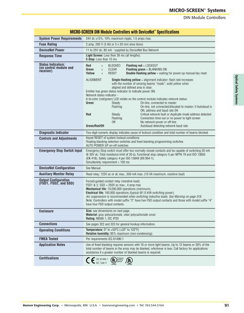
RRMICRO-SCREEN ® SystemsDIN Module <strong>Co</strong>ntrollersSystem Power RequirementsFuse RatingDeviceNet PowerResponse TimeStatus Indicators:(on control module andreceiver)MICRO-SCREEN DIN Module <strong>Co</strong>ntrollers with DeviceNet Specifications24V dc ±15%, 10% maximum ripple, 1.5 amps max.2 amp, 250 V (3 AG or 5 x 20 mm slow blow)11 to 25V dc; 80 mA - supplied by DeviceNet Bus NetworkLight Screen: Less than 38 ms (all lengths)E-Stop: Less than 15 msRed = BLOCKED Flashing red = LOCKOUTGreen = CLEAR Flashing green = BLANKING ONYellow = RESET Double-flashing yellow = waiting for power-up manual key resetALIGNMENT Single-flashing yellow = alignment indicator: flash rate increaseswith the number of sensing beams “made”; solid yellow whenaligned and defined area is clear.Emitter has green status indicator to indicate power ON.Network status indicator -A bi-color (red/green) LED visible on the control module indicates network status:Green Steady On-line, connected to masterFlashingOn-line, not connected/allocated to master; if Autobaud isON, address and baud rate OKRed Steady Critical network fault or duplicate mode address detectedGreen/Red/OffFlashingOff<strong>Co</strong>nnection time-out or no power to light screenNo network power or off-lineAutobaud detecting network baud rateOptical Safety SystemsDiagnostic Indicator<strong>Co</strong>ntrols and AdjustmentsEmergency Stop Switch InputDeviceNet <strong>Co</strong>nfigurationAuxiliary Monitor RelayOutput <strong>Co</strong>nfiguration(FSD1, FSD2, and SSD)Two-digit numeric display indicates cause of lockout condition and total number of beams blockedKeyed RESET of system lockout conditionsFloating blanking selection switches and fixed blanking programming switchesAUTO POWER UP on-off switchesEmergency Stop switch must offer two normally closed contacts and be capable of switching 50 mA@ 30V dc. Total resistance limit of 30 Ω. Functional stop category 0 per NFPA 79 and ISO 13850(EN 418), Safety category 4 per ISO 13849 (EN 954-1).Simultaneity requirement < 100 msSee Manual.Reed relay; 125V ac or dc max., 500 mA max. (10 VA maximum, resistive load)Forced-guided contact relay (resistive load).FSD1 & 2, SSD = 250V ac max., 4 amp maxMechanical life: 10,000,000 operations (minimum).Electrical life: 100,000 operations (typical @1.0 kVA switching power).Arc suppression is recommended when switching inductive loads. See Warning on page 319.Note: <strong>Co</strong>ntrollers with model suffix “2” have two FSD output contacts and those with model suffix “4”have four FSD output contacts.Enclosure<strong>Co</strong>nnectionsOperating <strong>Co</strong>nditionsCertificationsSize: see dimensions on next page.Material: gray polycarbonate, clear polycarbonate cover.Rating: NEMA 1, IEC IP20See pages 322 and 323 for general hookup information.Temperature: 0° to +50°C (+32° to 122°F)Relative humidity: 95% maximum (non-condensing)FMEA Tested Per requirements IEC 61496-1Application NotesUse of fixed blanking requires sensors with 16 or more light beams. Up to 12 beams or 30% of thetotal number of beams in the array may be blanked, whichever is less. Call factory for applicationsassistance if a greater number of blanked beams is required.IEC 61496-1&2, Type 4PresenceSensingDeviceBanner <strong>Engineering</strong> <strong>Co</strong>rp. • Minneapolis, MN U.S.A. • bannerengineering.com • Tel: 763.544.316491