pdf (2140k) - Adcon Engineering Co
pdf (2140k) - Adcon Engineering Co
pdf (2140k) - Adcon Engineering Co

Create successful ePaper yourself
Turn your PDF publications into a flip-book with our unique Google optimized e-Paper software.
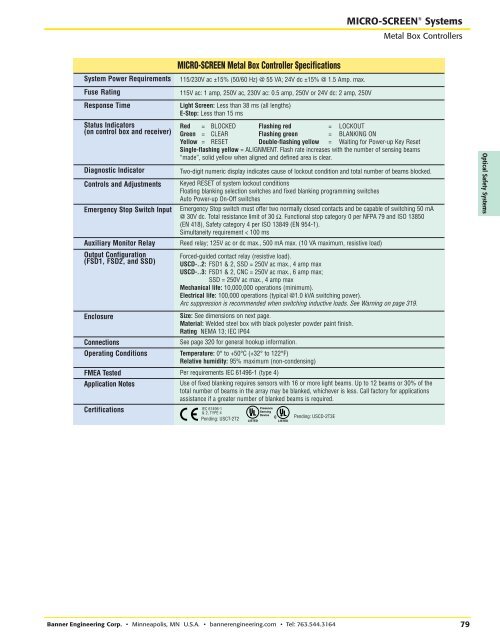
RRMICRO-SCREEN ® SystemsMetal Box <strong>Co</strong>ntrollersSystem Power RequirementsFuse RatingResponse TimeStatus Indicators(on control box and receiver)Diagnostic Indicator<strong>Co</strong>ntrols and AdjustmentsEmergency Stop Switch InputAuxiliary Monitor RelayOutput <strong>Co</strong>nfiguration(FSD1, FSD2, and SSD)Enclosure<strong>Co</strong>nnectionsOperating <strong>Co</strong>nditionsLight Screen: Less than 38 ms (all lengths)E-Stop: Less than 15 msSize: See dimensions on next page.Material: Welded steel box with black polyester powder paint finish.Rating NEMA 13; IEC IP64See page 320 for general hookup information.Temperature: 0° to +50°C (+32° to 122°F)Relative humidity: 95% maximum (non-condensing)FMEA Tested Per requirements IEC 61496-1 (type 4)Application NotesCertificationsMICRO-SCREEN Metal Box <strong>Co</strong>ntroller Specifications115/230V ac ±15% (50/60 Hz) @ 55 VA; 24V dc ±15% @ 1.5 Amp. max.115V ac: 1 amp, 250V ac, 230V ac: 0.5 amp, 250V or 24V dc: 2 amp, 250VRed = BLOCKED Flashing red = LOCKOUTGreen = CLEAR Flashing green = BLANKING ONYellow = RESET Double-flashing yellow = Waiting for Power-up Key ResetSingle-flashing yellow = ALIGNMENT. Flash rate increases with the number of sensing beams“made”, solid yellow when aligned and defined area is clear.Two-digit numeric display indicates cause of lockout condition and total number of beams blocked.Keyed RESET of system lockout conditionsFloating blanking selection switches and fixed blanking programming switchesAuto Power-up On-Off switchesEmergency Stop switch must offer two normally closed contacts and be capable of switching 50 mA@ 30V dc. Total resistance limit of 30 Ω. Functional stop category 0 per NFPA 79 and ISO 13850(EN 418), Safety category 4 per ISO 13849 (EN 954-1).Simultaneity requirement < 100 msReed relay; 125V ac or dc max., 500 mA max. (10 VA maximum, resistive load)Forced-guided contact relay (resistive load).USCD-..2: FSD1 & 2, SSD = 250V ac max., 4 amp maxUSCD-..3: FSD1 & 2, CNC = 250V ac max., 6 amp max;SSD = 250V ac max., 4 amp maxMechanical life: 10,000,000 operations (minimum).Electrical life: 100,000 operations (typical @1.0 kVA switching power).Arc suppression is recommended when switching inductive loads. See Warning on page 319.Use of fixed blanking requires sensors with 16 or more light beams. Up to 12 beams or 30% of thetotal number of beams in the array may be blanked, whichever is less. Call factory for applicationsassistance if a greater number of blanked beams is required.IEC 61496-1& 2, TYPE 4Pending: USCT-2T2PresenceSensingDevicePending: USCD-2T3EOptical Safety SystemsBanner <strong>Engineering</strong> <strong>Co</strong>rp. • Minneapolis, MN U.S.A. • bannerengineering.com • Tel: 763.544.316479