pdf (2140k) - Adcon Engineering Co
pdf (2140k) - Adcon Engineering Co
pdf (2140k) - Adcon Engineering Co

You also want an ePaper? Increase the reach of your titles
YUMPU automatically turns print PDFs into web optimized ePapers that Google loves.
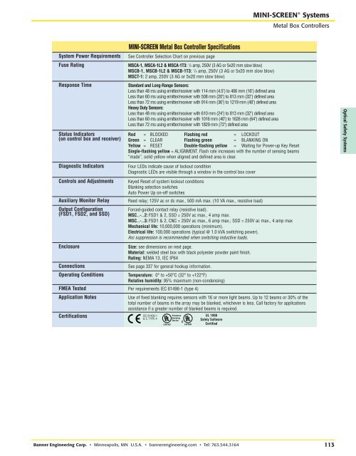
RRMINI-SCREEN ® SystemsMetal Box <strong>Co</strong>ntrollersMINI-SCREEN Metal Box <strong>Co</strong>ntroller SpecificationsSystem Power RequirementsFuse RatingResponse TimeStatus Indicators(on control box and receiver)Diagnostic Indicators<strong>Co</strong>ntrols and AdjustmentsAuxiliary Monitor RelayOutput <strong>Co</strong>nfiguration(FSD1, FSD2, and SSD)Enclosure<strong>Co</strong>nnectionsOperating <strong>Co</strong>nditionsSee <strong>Co</strong>ntroller Selection Chart on previous pageMSCA-1, MSCA-1L2 & MSCA-1T3: 1 /2 amp, 250V (3 AG or 5x20 mm slow blow)MSCB-1, MSCB-1L2 & MSCB-1T3: 1 /4 amp, 250V (3 AG or 5x20 mm slow blow)MSCT-1: 2 amp, 250V (3 AG or 5x20 mm slow blow)Standard and Long-Range Sensors:Less than 48 ms using emitter/receiver with 114 mm (4.5") to 406 mm (16") defined areaLess than 60 ms using emitter/receiver with 508 mm (20") to 813 mm (32") defined areaLess than 72 ms using emitter/receiver with 914 mm (36") to 1219 mm (48") defined areaHeavy Duty Sensors:Less than 48 ms using emitter/receiver with 610 mm (24") to 813 mm (32") defined areaLess than 60 ms using emitter/receiver with 1016 mm (40") to 1626 mm (64") defined areaLess than 72 ms using emitter/receiver with 1829 mm (72") defined areaRed = BLOCKED Flashing red = LOCKOUTGreen = CLEAR Flashing green = BLANKING ONYellow = RESET Double-flashing yellow = Waiting for Power-up Key ResetSingle-flashing yellow = ALIGNMENT. Flash rate increases with the number of sensing beams“made”, solid yellow when aligned and defined area is clear.Four LEDs indicate cause of lockout conditionDiagnostic LEDs are visible through a window in the control box coverKeyed Reset of system lockout conditionsBlanking selection switchesAuto Power Up on-off switchesReed relay; 125V ac or dc max., 500 mA max. (10 VA max., resistive load)Forced-guided contact relay (resistive load).MSC..-..2: FSD1 & 2, SSD = 250V ac max., 4 amp max.MSC..-..3: FSD1 & 2, CNC = 250V ac max., 6 amp max.; SSD = 250V ac max., 4 amp maxMechanical life: 10,000,000 operations (minimum).Electrical life: 100,000 operations (typical @ 1.0 kVA switching power).Arc suppression is recommended when switching inductive loads.Size: see dimensions on next page.Material: welded steel box with black polyester powder paint finish.Rating: NEMA 13, IEC IP64See page 337 for general hookup information.Temperature: 0° to +50°C (32° to +122°F)Relative humidity: 95% maximum (non-condensing)Optical Safety SystemsFMEA Tested Per requirements IEC 61496-1 (type 4)Application NotesCertificationsUse of fixed blanking requires sensors with 16 or more light beams. Up to 12 beams or 30% of thetotal number of beams in the array may be blanked, whichever is less. Call factory for applicationsassistance if a greater number of blanked beams is required.IEC 61496-1& 2, TYPE 4PresenceSensingDeviceUL 1998Safety SoftwareCertifiedBanner <strong>Engineering</strong> <strong>Co</strong>rp. • Minneapolis, MN U.S.A. • bannerengineering.com • Tel: 763.544.3164113