pdf (2140k) - Adcon Engineering Co
pdf (2140k) - Adcon Engineering Co
pdf (2140k) - Adcon Engineering Co

Create successful ePaper yourself
Turn your PDF publications into a flip-book with our unique Google optimized e-Paper software.
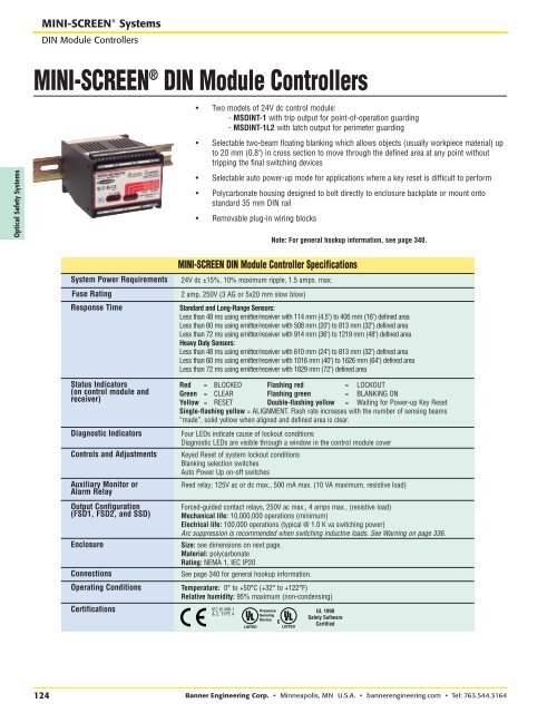
RRMINI-SCREEN ® SystemsDIN Module <strong>Co</strong>ntrollersMINI-SCREEN ® DIN Module <strong>Co</strong>ntrollers• Two models of 24V dc control module:- MSDINT-1 with trip output for point-of-operation guarding- MSDINT-1L2 with latch output for perimeter guarding• Selectable two-beam floating blanking which allows objects (usually workpiece material) upto 20 mm (0.8") in cross section to move through the defined area at any point withouttripping the final switching devicesOptical Safety Systems• Selectable auto power-up mode for applications where a key reset is difficult to perform• Polycarbonate housing designed to bolt directly to enclosure backplate or mount ontostandard 35 mm DIN rail• Removable plug-in wiring blocksNote: For general hookup information, see page 340.System Power RequirementsFuse RatingResponse TimeStatus Indicators(on control module andreceiver)Diagnostic Indicators<strong>Co</strong>ntrols and AdjustmentsAuxiliary Monitor orAlarm RelayOutput <strong>Co</strong>nfiguration(FSD1, FSD2, and SSD)Enclosure<strong>Co</strong>nnectionsOperating <strong>Co</strong>nditionsCertificationsMINI-SCREEN DIN Module <strong>Co</strong>ntroller Specifications24V dc ±15%, 10% maximum ripple, 1.5 amps. max.2 amp, 250V (3 AG or 5x20 mm slow blow)Standard and Long-Range Sensors:Less than 48 ms using emitter/receiver with 114 mm (4.5") to 406 mm (16") defined areaLess than 60 ms using emitter/receiver with 508 mm (20") to 813 mm (32") defined areaLess than 72 ms using emitter/receiver with 914 mm (36") to 1219 mm (48") defined areaHeavy Duty Sensors:Less than 48 ms using emitter/receiver with 610 mm (24") to 813 mm (32") defined areaLess than 60 ms using emitter/receiver with 1016 mm (40") to 1626 mm (64") defined areaLess than 72 ms using emitter/receiver with 1829 mm (72") defined areaRed = BLOCKED Flashing red = LOCKOUTGreen = CLEAR Flashing green = BLANKING ONYellow = RESET Double-flashing yellow = Waiting for Power-up Key ResetSingle-flashing yellow = ALIGNMENT. Flash rate increases with the number of sensing beams“made”, solid yellow when aligned and defined area is clear.Four LEDs indicate cause of lockout conditionsDiagnostic LEDs are visible through a window in the control module coverKeyed Reset of system lockout conditionsBlanking selection switchesAuto Power Up on-off switchesReed relay; 125V ac or dc max., 500 mA max. (10 VA maximum, resistive load)Forced-guided contact relays, 250V ac max., 4 amps max., (resistive load)Mechanical life: 10,000,000 operations (minimum)Electrical life: 100,000 operations (typical @ 1.0 K va switching power)Arc suppression is recommended when switching inductive loads. See Warning on page 336.Size: see dimensions on next page.Material: polycarbonateRating: NEMA 1, IEC IP20See page 340 for general hookup information.Temperature: 0° to +50°C (+32° to +122°F)Relative humidity: 95% maximum (non-condensing)IEC 61496-1& 2, TYPE 4PresenceSensingDeviceUL 1998Safety SoftwareCertified124 Banner <strong>Engineering</strong> <strong>Co</strong>rp. • Minneapolis, MN U.S.A. • bannerengineering.com • Tel: 763.544.3164